
PicoCount 2500 Traffic Counter Manual
Last Updated 08/23/2013
Table of Contents
1.4 Starting TrafficViewer Pro.
1.5 Connecting to your counter.
2.1.4.3.1 Single Hose -- Single Lane, or Multi-Lane.
2.1.4.3.2 Two Hoses Median Mounted, or Long Hose / Short Hose connected.
2.1.4.3.3 Dual Hose Speed/Classify Setups.
2.2 Setting up PicoCount 2500.
2.2.1 Clearing the PicoCount Data.
2.2.2 Attach the hoses to the PicoCount 2500.
2.2.3 Verify the hose connections.
3.0 When Things Don't go Right.
3.1.1 Volume only counts with a single hose reading zero.
3.1.2 Volume only counts with a single hose reading low.
3.1.3 Volume only counts with a single hose reading high.
3.1.4 Volume only count errors with long hose - short hose configuration.
3.1.5 Speed or Class count errors with two hoses -- single lane.
3.1.6 Speed or Class count errors with two hoses -- multi lane.
This manual is available in full color PDF format at this manual download.
The VehicleCounts.com PicoCount 2500 vehicle counter raises the bar for vehicular traffic counters. With its incredible 250Mbyte+ memory, high resolution timestamps, over 10 year battery life, and its no-setup-required operation, the PicoCount 2500 sets the standard for 2 channel air hose counters. The Picocount interfaces directly to your PC using TrafficViewer Pro software for data downloads, unit configurations, reports and data exports. The TrafficViewer Pro software is free and is available here or if you wish to use the “Beta” version, you can get it from beta.
This manual is written with the assumption that you are familiar with automated traffic counters, their setup and usage. It also assumes you are familiar with the terminology used in the traffic counting industry. The operations section of this manual walks through all the steps of operating your PicoCount 2500 counter. Each operation is described in some detail to help you understand normal usage. If you wish to know more, detailed descriptions of all options are covered in the TrafficViewer Pro Software Manual which you can get a copy of from here.
Anchor. The device used to secure the air hose to the roadway or shoulder.
Dwell. The time after a hose is “hit” before another “hit” will be recorded. Also known as deadtime, recovery time, response time, delay after hit time, etc. In the case of timestamp recording machines like the PicoCount, the dwell time can be adjusted after the data is collected to aid in cleaning up the collected data. In these machines there is also a minimum settable dwell time which is the built in hardware delay time that all timestamp data is collected with.
Grip. The device used to attach the air hose to the anchor device.
Hit. When a moving vehicle tire strikes a hose generating an air pulse.
Hose. Specifically, the rubber air hose (pneumatic hose) used by the PicoCount 4500 for traffic sensing.
Multiple-Study. Several traffic studies done without downloading the data between studies.
Occupancy. In multi-lane roadways, it is the total of vehicles in each lane.
Roadway. The active surface of the highway, road, or driveway that vehicles travel on.
Study. The setup and collection of roadway data in one session. In other words, if you reset the PicoCount counter, set it up on a roadway, collect the data, then download the data, you have completed a study. If you set the counter up and collect data more than one time before downloading the data, then you have collected multiple studies.
Timestamp. A data storage method where every event (such as a hose hit) is recorded as a time count.
Traffic Study. In our case, it is the data gathered for a period of time. There are a variety of other terms used in the industry for the same thing, such as "Session", "Counts", or just "Study".
The following trademarks are used throughout this manual:
Windows® is a registered trademark of Microsoft Corporation.
PicoCount is a trademark of R&R Technologies, Inc.
TrafficViewer Pro is a trademark of R&R Technologies, Inc.
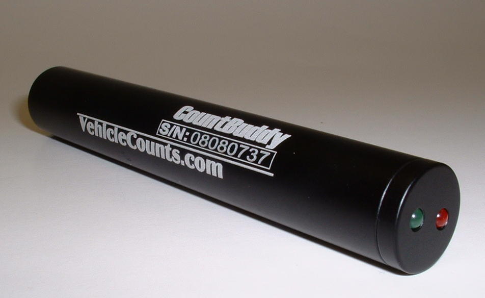
CountBuddy is a trademark of R&R Technologies, Inc.
VehicleCounts.com is a trademark of R&R Technologies, Inc.
If you are using the USB download cable, the first thing you will need to do is install drivers for it. The USB driver install program may be downloaded from our website at www.vehiclecounts.com/downloads.html.
To determine if you will need to install drivers, plug the download cable into your PC. You will see a Windows info screen pop up saying "New hardware found".
If you are lucky, Windows will recognize the USB download cable and automatically install/activate the drivers and you will see a Windows info screen pop up saying "Hardware installed and ready to use". If this is the case, you are ready to proceed.
If Windows does not recognize the USB device or the appropriate drivers, the driver install wizard should pop up. Close the wizard. Then download and run the Driver Install program from our website. Once the installation is complete, the USB download cable should properly connect each time you plug it in.
Make sure the USB download cable is connected before starting TrafficViewer Pro software. The TrafficViewer Pro software scans for all Windows® serial port connections (including USB) as it starts, if a new Windows® serial connection is made after the software is running, the software will not be aware of the serial connection.
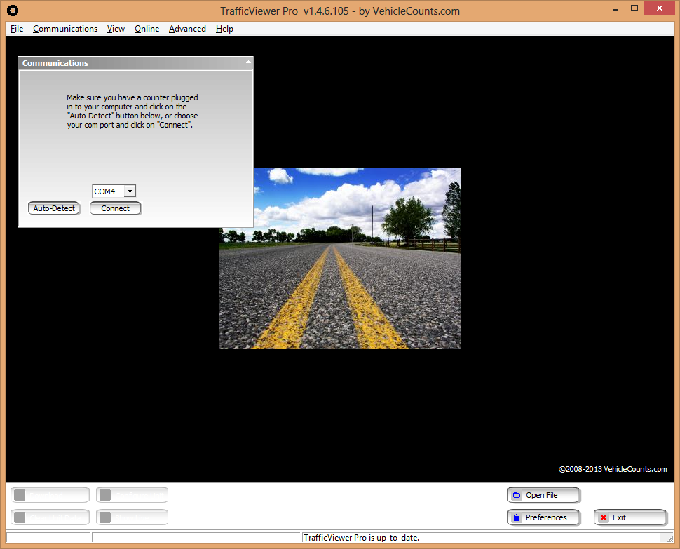
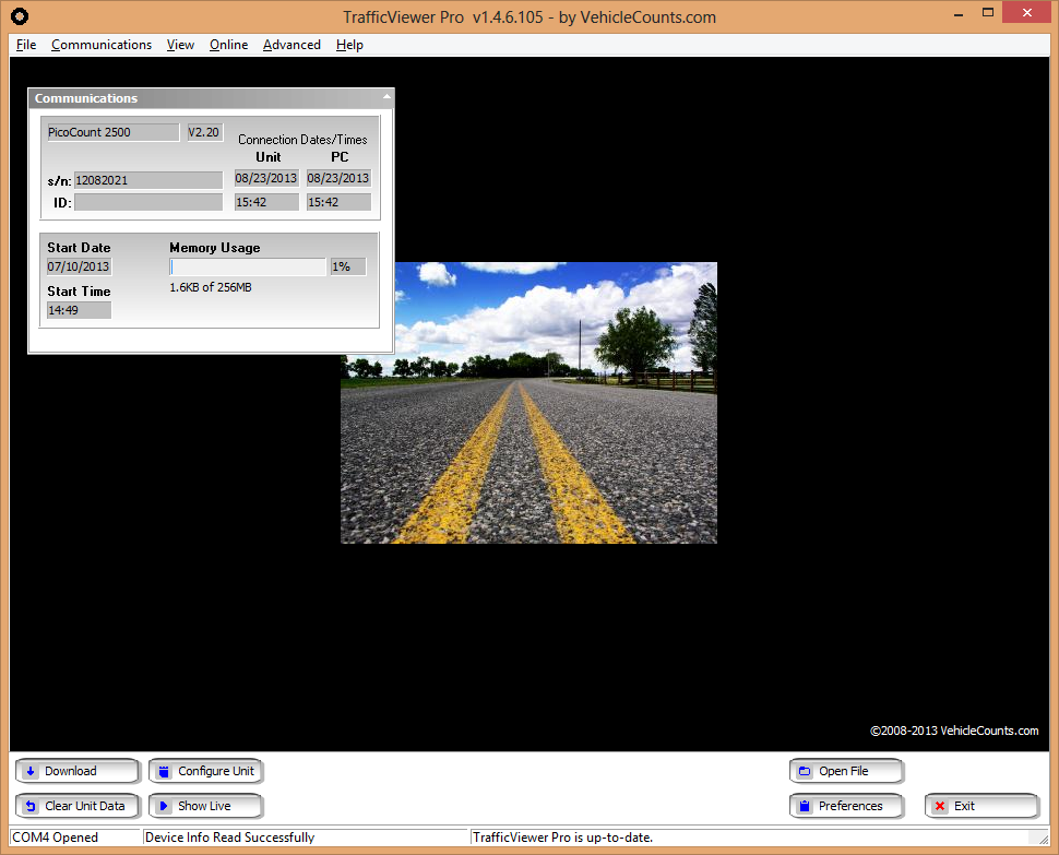
Upon starting TrafficViewer Pro software, you should see the following window, the TrafficViewer Pro desktop:
Occasionally, you might see the screen below pop up first, if so, just click on "Close" when it has finished (discussed in detail in the TrafficViewer Pro manual).
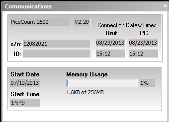
Connect your counter to your PC with the download cable. Then click on "Auto-Detect" in the Communications dialog box:
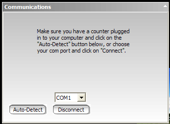
After a few seconds the communications dialog box should show the PicoCount connection status similar to below:
Once this screen appears, you need to clear the data in the counter by clicking on the "Clear Unit Data" button in the lower left of the TrafficViewer Pro screen.
![]()
The following dialog will pop-up:
Click on "Yes".
Clearing the unit data insures that any current data in the machine is discarded and most importantly that the date/time is synchronized with your PC. As a practice, you should always clear the counter’s data before setting it out for counts. This insures that you only have one study (or session of data) and it keeps the counter’s built-in clock "synchronized" with your PC.
You are now ready to set the counter out for counting. The PicoCount counters have no power switches and are ALWAYS counting, though no memory gets used if there are no "hits" on the air switches.
This section discusses the operation of the PicoCount 2500. It discusses how to set out the air hoses, how to configure the air hoses for various types of studies. Getting the counter ready for a study, setting the counter out for a study, and processing the study results.
The one of the most important factors in getting good counts with air hose counters is in proper setting of the hoses, so that is where we start, but first a little education.
Air hose comes in a variety of sizes, shapes and materials. For traffic counting though there are only a few to consider.
Choosing a material:
All air hose used in traffic counting is made of natural rubber or a synthetic rubber referred to as EPDM.
Natural rubber is softer than EPDM rubber for a given thickness and hole size. Therefore, natural rubber is slightly easier to handle and store.
Natural rubber can be degraded by exposure to UV from sunlight, whereas EPDM has been formulated to be resistant to UV degradation.
For hot temperatures, EPDM is the preferred rubber, and for cold temperatures natural rubber is the preferred rubber. EPDM is the most popular rubber used because it performs well over a wide temperature range from hot desert conditions down to near freezing whereas natural rubber performs best from warm temperatures down to well below freezing.
For a given hose size and length, signal attenuation in natural rubber is slightly higher than EPDM, which means that EPDM is better for long hose runs.
In the USA, natural rubber is mainly considered a "winter" hose, and is mainly used in the northern latitudes.
Choosing a size and shape:
There are currenly three shapes of hose in use today; round, half-round, and dual-hose.
![]()
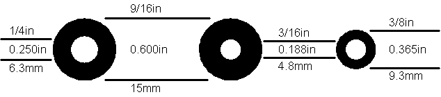
Round is by far the most popular and easiest to use. It is suitable for the majority of counting applications. There currently are two sizes which are most common, normal hose and mini hose.
Normal hose is about 15mm outside diameter (9/16 inch or 0.600 inch). It comes with either a 6.3mm hole (1/4 inch or 0.250 inch), or a 4.8mm hole (3/16 inch or 0.188 inch).
Mini hose is about 9.3mm outside diameter (3/8 inch or 0.365 inch). It comes with a 4.8mm hole (3/16 inch or 0.188 inch). The profiles of these three styles are summarized below:
The normal hose with the 6.3mm hole has good resistance to wear and generates the strongest air pulses. It is the preferred hose in very long hose runs.
The normal hose with the 4.8mm hole is stronger, stiffer and heavier. It is intended for very heavy traffic conditions, or where there is a lot of truck traffic. It also would be the hose of choice for unimproved and gravel roads. The air pulse it generates is weaker than the hose above, so longer runs are not practical.
The mini hose is fairly recent as an air hose, but has rapidly become the hose of choice. It generates a smaller air pulse than the normal hose with the larger hole, so it is not suitable for long hose runs. It's biggest appeal is that it is quite a bit lighter and more pliable than the normal hose. If you are setting out lots of counters each day, it can save a lot of labor. The mini hose does not hold up as well to traffic wear as the normal hose.
As a rule of thumb, in a very busy count program, normal hose will usually last a full count season (in most areas a count season goes from spring through fall) before needing replacement. Mini hose on the other hand may only last half a season before needing replacement.
Half-round, because of its beefier build, finds use in very heavy traffic, where there is a lot of heavy truck traffic, or where the hoses are going to be left out for extended count times. This hose is trickier to lay down on the road, the flat side must always face the roadway, and it is pretty difficult to handle.
Dual-Hose is relatively new. It is generally constructed of two mini hoses with a webbing in between that maintains the hoses at a fixed, close, spacing. This hose must be mounted to the roadway with it's flat side against the pavement. It is more complex to attach to the roadway, and harder to handle, but is a much more reliable way to place down two hoses at one time. This hose can only be used, for speed and classifying, with the newest generation of traffic counters that have the time resolution to give satisfactory results.
This section describes the various methods used to attach the hose to and near the roadway. Proper attachment of the hose is very important to getting proper counts.
Methods of Attachment:
There are a variety of methods used to attach hoses to the roadway and shoulders. We will discuss each of these methods along with their pros and cons. Attaching a hose involves two distinct operations, placing an anchor and gripping the hose.
Anchors:
An anchor is the device attached to the roadway or shoulder that the hose will be attached to.
There are several devices used for anchors. Choice of the anchor device will depend on several factors, like roadway surface material, shoulder surface material, roadway temperature, etc.
To determine the appropriate anchor device, you need to decide where the anchor points will be placed. When stringing hoses on roadways, ideally the anchoring is off the roadway surface, on the shoulders, however, this often not possible. Generally, the traffic counter unit will be mounted next to the roadway and the hoses will be strung across one, two, or more lanes of roadway. The end nearest the counter on most roadways can easily be anchored in the shoulder, except when they are cement sidewalks, or the shoulders are extremely soft, or non-existent. The far end of the hose must often be anchored in the middle of the roadway, depending on the hose configuration for the study you will be doing.
Choice of the anchoring device depends on the materials it must be mounted to. For shoulder anchoring, the materials will generally be compacted gravel and soil, or tarmac. For roadway anchoring, the materials will be tarmac or cement. Tarmac is easier to drive nails into when it is warmer whereas cement doesn't care about temperature, it is always hard.
The most common anchoring device is the nail. For tarmac roadways you would use tarmac nails, masonry nails, or PK nails. For soft shoulders you would use spikes which come in a variety of lengths from 150mm (6 inches) to 300mm (12 inches) depending on the firmness of the shoulder. You will need a pretty hefty hammer for driving in the nails or spikes. In tarmac, you can also use power nails and an anchor plate with a portable nail gun (not common, but quick). [a]
Another form of anchoring device is the masonry screw. This would be mostly used in sites that are re-visited quite often, such as on-ramps to freeways, etc. This involves drilling a hole then hammering the screw anchor into the hole.
In tarmac in warmer climates you can directly screw into the tarmac with the proper screw and power screwdriver.
Anchoring in tarmac depends on the weather. When it is hot, the tarmac is soft and the anchoring devices must be longer to stay put. Sometimes it may be necessary to also use an anchoring plate held down by several nails. When it is cold, the tarmac can become very hard and shorter anchoring devices would be used[b].
Grips
A grip is the device used to attach the hose to an anchor. There are a variety of methods used for this purpose and we will discuss the pros and cons of each here. A hose has two ends, one end is terminated in the traffic counter and the other end is at the far end of the roadway or lane being measured. The grip at the roadway shoulder must attach to the hose in such a way that the hose is not pinched shut, yet it must hold the hose firmly enough that it will not slip. The grip at the far end of the hose (from the counter) simply has to hold the hose from coming loose from the anchor. We are going to discuss five different types of grips: Chinese fingers, figure-8, C-clamps, anchor-plate clamps, Nylon belt, and Nylon cord.
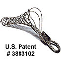
Chinese fingers are made from stainless steel wire formed into a patented web pattern that grips the hose in such a way that it will not pinch shut, and it will not slip. This is great for the counter end of the hose. These devices can also be very quickly attached to the hose and allow simple tension adjustment. In heavy traffic situations where you do not want to be out in the roadway any longer than possible, these devices can be a life saver. These are the highest cost grips we will discuss. In very hot climates, the rubber hose can get so soft that these types of grips can actually sever the hose since they are made from a narrow gauge stainless steel wire. You must get the correct size of grip for the hose thickness you will be anchoring. This type of grip can be attached to the anchor in two ways: You can pre-install the anchor and simply loop the anchor end of the grip over the nail-head. Once under tension, this grip will not normally pop off. The other method would be to use a large washer and drive the anchor nail through the washer and the anchor loop of the grip. This later method may be necessary in high speed traffic. However proper usage of road tape can solve the hose bouncing issue.
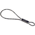
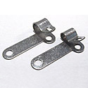
Figure-8 grips are made from a thicker gauge of stainless steel formed into a loop that is pinched near one end (looking like an unbalanced figure 8). These grips are easy to attach to the hose and adjust. They grip over a wide enough area that they normally will not pinch the hose shut. They also will hold without slipping once the hose is under tension. If the hose is bouncing a lot in traffic, slippage may occur. Appropriate application of road tape (discussed below) can prevent this. This type of grip can be attached to the anchor in two ways: You can pre-install the anchor and simply loop the anchor end of the grip over the nail-head. Once under tension, this grip will not normally pop off. The other method would be to use a large washer and drive the anchor nail through the washer and the anchor loop of the grip. This later method may be necessary in high speed traffic. For the hose end grip, you can apply some duct-tape over the grip, after it has been attached and the hose is tensioned, to prevent slippage. This type of grip is of moderate cost. This can also cut into the hose in hot temperature.
The C-clamp grip is good for the far end of the hose when it must be attached in the middle of a roadway. These grips are made of galvanized steel. This type of grip is first attached to the hose, then an anchor nail is driven through one or both of its mounting holes. You would use two holes in warmer climates when the tarmac is getting softer. This type of grip can pinch the hose shut so would not be considered for the shoulder grip. Since the anchor is installed through this grip, you must spend more time in the roadway installing it, especially if you have to drive in two anchors. This grip is of moderate cost.
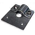
The anchor plate is used for the far end of the hose when it must be mounted in the middle of the roadway and the tarmac is very soft from hot temperatures. Anchor plates are made of a thick gauge of galvanized steel and have 4 mounting holes. You can spend considerable time in the roadway installing this type of grip, particularly if you are using all of the mounting holes. Anchor plate grips pinch the hose shut. You must specify the hose size when purchasing the anchor plate. If the anchor plate grip ever comes loose, you have a fairly good size chunk of metal loose in the roadway which could cause damage to vehicles. The anchor plate grip is moderate to high cost.
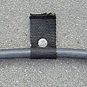
The Nylon belt grip is made by cutting off a 10 to 15 cm ( 4 to 6 inch) length of the belt, folding it around the hose and driving a nail through it into the roadway. It is only useful as a grip at the far end of the hose. It cannot prevent slippage, therefore the end of the hose has to be large enough not to slip through the grip, this is usually accomplished by tying the end of the hose into a knot (see end-plugging the hose below). This can be a low cost grip, but you have to buy a roll of the belt and cut it into grips.
Grips made of Nylon[c] cord are very popular, namely because they are cheap. You cut off a strip of cord and literally tie the hose to the anchor. Once you get the hang of tying proper knots to prevent pinching the hose, these type of grips can be as effective as the figure-8 types of grips. This type of grip has a real advantage in very hot weather, because the Nylon is relatively soft and flattens out under tension, it will not cut into the rubber as it gets soft. This type of grip is the least expensive, but does require proper knot tying to not have problems. For the hose end grip, it is a good idea to apply some duct-tape over the knots after they have been attached and the hose is tensioned to prevent slippage.
To prevent moisture, dirt, and grit from entering the hose, the far end needs to be plugged. Moisture in the hose can block the airway, whereas dirt and grit inside the hose can cause rapid breakdown of the hose, by lacerating the inside surface when vehicles compress the hose as they are driving over it. Dirt, grit, and hose particles can eventually get vibrated all the way down to the air switches and cause the air switches to become clogged and non-functional. One exception to plugging the end of the hose is in very hot temperatures, particularly when the day to night temperature extremes are large. In this case, a very small pinhole in the end-plug is recommended to keep the air pressure inside the hose normalized. We will discuss a variety of methods to plug the end of the hose.
Tying a knot[d] at the end of the hose. For the mini hose this is very easy to do. Depending on the stiffness of the normal hose being used, this may or may not be an option. It is a common method used. The big knot makes using C-clamps or Nylon belt grips easy, since it will not slip through them. If the hose is terminated in the middle of the roadway, the big knot might be objectionable. In very hot conditions, the knot would not accomodate a breather hole.
Hex-head [e]bolts made of galvanized steel, stainless steel, or Nylon, which you can pick up at local hardware store, can make a good end-plug. You have to choose the proper size thread for the center hole of the hose. The hex-head makes it easy to get leverage when threading the bolt into the hose. If you are needing breather holes, this scheme will not work. These are low cost.
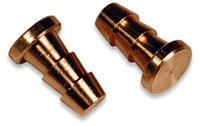
Commercial brass end-plugs. These devices are barbed and just press into the end of the hose. You have to specify what size center hole they are designed for. These can be purchased with a pin-hole for hot temperature use. These are high cost, more so when a pin-hole is needed.
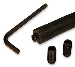
Commercial threaded end-plugs. These devices are threaded like the bolts mentioned above, but use an Allen drive to thread them in. They are made of anodized steel. They do not have the big head of the hex-head bolt, so present less of a hazard should they come loose on the roadway. You must specify what size center hole you will be plugging. These are of moderate cost.
This section will describe the various ways to set out hoses for the different types of studies you will be doing. When setting out hoses, there are a few rules of thumb to keep in mind.
After you have anchored and set down your hose, you will need to put it under tension so that it lays straight across the roadway. With normal hose, you need to pull the hose tight, then stretch it about 10% more (for a single lane, you will need to stretch it about 30cm or one foot).
If you are using mini hose, you just pull it up tight, do not attempt to stretch it.
When setting down hose, the hose is normally anchored in two spots, the far end of the hose and at the roadway shoulder on the near end. If the traffic is moving at high speeds, you may notice that your hoses are moving noticeably when vehicles travel over it. If this is the case, you will need to consider taping the hose at spots between the anchors. Mini hose tends to move easier since it is under less tension. If the wheel tracks have deep depressions, that can also make the hose move, even at moderate speeds. Note, that when taping down the hose, do not tape in the wheel tracks; avoid taping anywhere wheels would normally run over the hose.
There are two types of tape used for this purpose. Black duct-tape and Mastic tape. Both are fiberglass reinforced, both are very tough.
The Mastic tape has a very thick coating of tar and a very strong adhesive. It can be very difficult to remove at the end of a study, and leave the hose rather sticky. Being mostly tar, this tape can be left on the roadway where it will eventually merge into the roadway. This type of tape really only works well in warmer conditions where it begins merging into the tarmac. It can be applied to wet roadways that are warm, and bond well. In cold climates, it is too stiff and as a result, does not handle well, or bond well to the roadway.
Duct-tape is very thin and has a strong adhesive. This tape is easy to apply. It adheres reasonably well to clean, dry surfaces. Since it does not merge into the tarmac, it does not form nearly as strong a bond as the Mastic tape. In cold climates, it is about your only choice. It will stay down okay for a day or so, depending on traffic loads, but it is not very useful for long studies.
If you need center attachment to keep the hoses from moving and taping is not going to work, you can anchor the middle points using Nylon belt grips.
This section discusses the various configurations of hose placements, based on the type of study you will be doing. We will discuss the placements of hoses for volume only studies, followed by placements of hoses for Speed/Class studies. For volume only counting we will discuss the most common configurations, single hose, two hoses median mounted, and two hoses long-hose/short-hose.
Often only a single hose is required for volume only counts, depending on the end need of the consumers of the count data. A single hose can be strung across only one lane, or multiple lanes for a single count that is the sum of the traffic in all the lanes (less hose hits that are hidden by other hose hits occurring at nearly the same instant).
Single hoses stretched across multiple lanes will count quite well in low to medium traffic loads, but as the total traffic in vehicles per hour increases, the occurrences of simultaneous hits increases and as a result, the traffic volume being determined by the counter will be lower than reality. For example, with a default dwell time set at 55ms (recommended for volume only counts), at 1000 total vehicles per hour in all lanes, the total volume recorded would be about three percent low. This could actually get worse if the multi-lane counts are being done between signal lights, because the traffic would be coming in groups with the chances of simultaneous hits considerably increased.
There are a couple of configurations where two hoses are used in volume only counts. The dual hose setup with the counter mounted in the medium is pretty common, especially for split roadways and freeway exits. The dual hose setup for a multi-lane roadway utilizing a short hose and a long hose is a common way of getting volume counts for both directions.
In the long hose - short hose setup shown above, the short hose is stretched across the nearest lane only and the long hose is stretched across the full roadway. The spacing between the hoses is not critical and can be anything convenient. Likewise, since this is a volume only setup, hose lengths are not critical. [g]
Whenever you want speed and/or vehicle classification, you need to use two hoses. There are a few rules that you need to follow so that your speeds and classifications are properly calculated.
The PicoCount counters can accommodate a wide variety of hose spacings (L) and calculate good results. Generally, you will have a standard hose spacing that you use for all your different counters. You can specify this default spacing in the preferences dialog of TrafficViewer Pro, so that it does not have to be set for each study.
The accuracy of the speed calculation (and hence the classifications) depends on the parallel hoses being maintained at a precise spacing. For example, if your default hose spacing is 100 centimeters, a one centimeter error in hose spacing would cause a one percent error in the calculations. Or if your default hose spacing is 36 inches, a one inch error in hose spacing would cause about a three percent error in the calculations.
The problem of maintaining accuracy gets more difficult with closer spacings. For example, if your default hose spacing is 10 centimeters, a one centimeter error in hose spacing would cause a 10 percent error in the calculations. Or if your default hose spacing is 6 inches, a one inch error in hose spacing would cause about a 17 percent error in the calculations.
The diagram above shows a multi-lane setup for speed and classification. Although it is possible to do this, we do not recommend it. For the most accurate results, speed and classification should only be done on a single lane. The multi-lane configuration should only be considered on very low volume roadways where the average total volume is below 100 vehicles per hour. The problem occurs when two vehicles are going over the hoses at or near the same times it can be very difficult to determine which hits belong to which vehicle leading to potential speed miscalculations and classification calculations. This setup works well for many rural and neighborhood surface streets. The lanes can being monitored can be moving in the same direction, or in opposite directions (as shown above).
Now that you have the hoses set up, you need to connect up your PicoCount 2500. As noted previously, the PicoCount 2500 is always counting, there are no switches to worry about, you just need to connect the counter up to the hoses for counting to begin.
Unless you are deliberately doing a multiple study, you should clear the data in your PicoCount 2500 before each study after you download the prior study data. If this is not done, it will not affect the operation of the PicoCount in any way, but you will end up with two studies of data in the counter and have to sort it out when generating your reports. To reset the PicoCount, it needs to be connected to a computer with TrafficViewer Pro running (see above). Clearing the data in the counter also sets the counter's date/time to the current date/time of the computer the PicoCount is connected to.
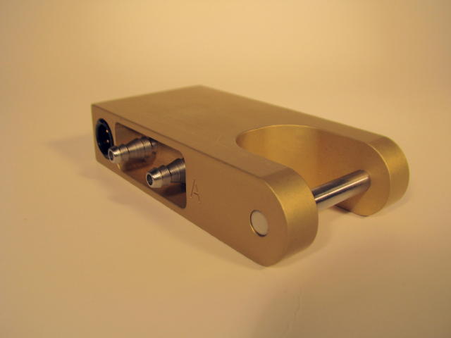
Note that there is a letter "A" embossed into the PicoCount 2500 on the side facing the barbs. The barb nearest is the A hose input. If your hose setup requires a specific hose attachment to the A or the B input you can now attach it accordingly. The PicoCount 2500 hose barbs are designed to take hoses with 4.7mm and 6.3mm (3/16inch and 1/4inch) center holes. In the case of the 6.3mm (1/4inch) holes, the hose needs to be pressed all the way flush to the case to insure a good grip. For the 4.7mm (3/16inch) holes, press the hose on until if firmly resists further pressing. If you are only doing a single hose volume count, make sure to cap the unused input barb so[h] that water and grit does not get into the unused channel.
If you have purchased a CountBuddy, you can easily verify that the PicoCount 2500 is detecting and counting hose hits correctly. Once the hoses are connected, simply plug the CountBuddy into the communications connector on the PicoCount 2500. When you first attach the CountBuddy, both LEDs (Red and Green) will blink together, once, to indicate that it is communicating with the PicoCount 2500. Now whenever a vehicle drives over the hoses, the appropriate LEDs will blink (Green is A hose, Red is B hose). If the LEDs are blinking correctly, then data is being recorded correctly and your hose connections are good. If the LEDs are not blinking as expected, check you hose connections very carefully for correct seating, pinching of the hoses at the grips, or splits and tears in used hose.
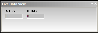
Alternatively, if you have a laptop or a netbook handy, you can connect to the PicoCount 2500 with TrafficViewer Pro and click on "Live Data View". A pair of counters will pop up (See Live Data View description above) showing the total of the A hose hits and the B hose hits since you started the Live Data View. These counter show the actual axle hits, so for a car, you should see both the A and the B counts advance by 2 each time a car runs over the hoses.
Normally, at the end of a study, you would disconnect the PicoCount from the hoses and take the counter back to your sevice vehicle or office to download the data. However, you can download the data at any time, even while the PicoCount unit is connected up gathering data, if you have a laptop with TrafficViewer Pro installed.
Once your study is complete and you have disconnected the PicoCount from the hoses you are ready to download your data. Next connect the PicoCount, with the appropriate download cable, to your PC running TrafficViewer Pro. Then begin communications with the PicoCount by clicking on the Auto-Detect or the Connect button.

Once communications is established with the PicoCount, click on the action button Download, located in the lower left of the TrafficViewer Pro desktop, which should now be active.
Once you click on Download, a progress panel will pop up showing the progression of the download. For short data files you may only see the Download Completed panel.
As soon as the download is complete a Data Setup panel will pop-up.
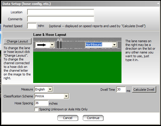
When this panel pops up, you may enter the desired data into the fields Location, Comments, and Posted Speed. These fields are optional. These fields if filled out will show up in all reports, exports and saved data files. The Posted Speed is also used by the Calculate Dwell button discussed below.
Next specify the Lane & Hose layout that you used for the study. If the desired layout is not displaying on the screen, then click on Change Layout and the following window will pop up.
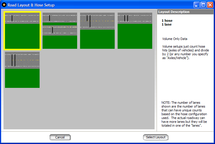
Highlight the hose setup that best represents how you had the hoses set up for the study then click on “Select Layout”. In this example, we were collecting volume data with a single hose on a single lane traveling North. the first layout (shown highlighted).
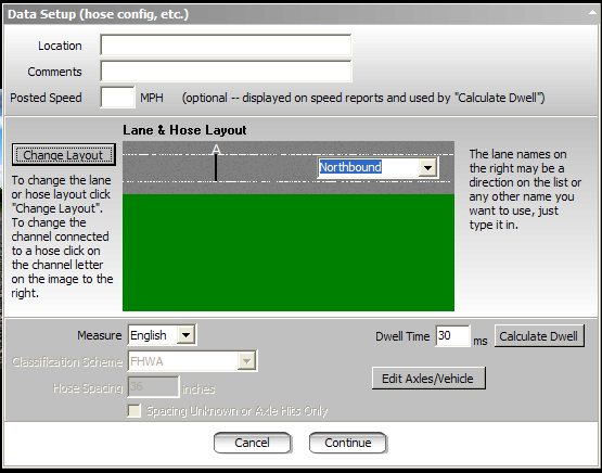
The “Data Setup” screen now shows your hose layout. Next you need to specify the traffic flow in each lane by selecting the appropriate names for the directions. Then verify that the hose connections for the layout are what you had set up. In this example hose A and B were connected to the upper lanes with hose A being the long hose, and hose B being the short hose. Hose C and D are connected to the lower lanes with Hose C being the short hose and D being the long hose. If the hose connections are not right, you can click on the letter (A,B,C,D) above the hoses and change them to the correct channels on the counter. Caution! Make sure that you do not have the same channel specified for more than one hose when you are ready to “continue”, otherwise you may get unexpected results.
Once the hose layout and configuration is done fill in the remaining fields. These fields will generally always be the same from study to study. The default settings that you usually use can be set in “Preferences”.
Measure indicates how your data, is to be presented, either in English measurements (inches, MPH), or in Metric measurements (centimeters, KPH). this setting also dictates how dates are displayed (English - MM/DD/YYYY, or Metric - DD/MM/YYYY).
Dwell Time (or dead time) is the delay time after a hose hit before another hose hit can be recognized. You can change any of these values if you need to for the study you have just downloaded, this is discussed below in the When things don’t go right section. There is a Calculate Dwell button which is useful for generating an appropriate dwell time for your particular hose setup and the Posted Speed field in the top part of the form.
Clicking on Edit Axles/Vehicle brings up a small dialog which will allow you to specify the average number of axles per vehicle in your collected data. Usually, these would be left a 2. These are only used in volume only counting. This is dscussed in more detail below in When things don’g go right section.
Spacing Unknown or Axle Hits Only is a checkbox would only be checked if you have a layout specified that is capable of doing speeds and classifications, but you are only doing volume counts. An example of this would be if you are setting two hoses across one lane only, but are only after volumes (which one hose would do), but you want the redundancy of the two hoses, just in case one breaks or comes loose. Note, this field will be greyed out if you choose one of the volume only layouts as we have here in our example.
Please note that any changes you make to the settings in this panel have a temporary memory and will be used for any following downloads as long as TrafficViewer Pro is kept open. If you are not sure of all the correct settings, you can continue on anyway, and come back to this screen later from the Data Overview panel, even after saving the data. Settings on this screen in no way affect the “raw” data, only the computed “results” data. So if a mistake is made on this screen, simply returning to this screen and making the correction will fix the problem without having to reload the data. Another thing to keep in mind, is that when you “save” the data in the Data Overview screen, all of the settings from this screen will be saved along with the file, so that when you reopen the data file you will not need to visit this screen unless you want to change some of the settings.
Once the panel represents your study data correctly, you may click on the Continue button.
The Data Overview will now pop up and you will see a panel similar to the one below.
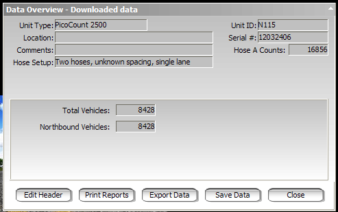
The top section of the panel should show the file information about the study that you entered plus the PicoCount 2500 serial number and user ID field, and the middle of the panel will show a data summary of the study you just completed. Use the data summary to determine if the collected study is about what you would expect. There is also a Data Quality meter which gives you the computers approximation of the expected quality of the data based on several factors such as missing or extra axle hits. If the data summary seems incorrect or the Data Quality meter is not reading very well, you can click on Edit Header and review and change your hose setups and directions to correct the problem.
Note! It is highly recommended that after a successful download, and before printing any reports, that you save the raw data. It is easy to do, and if for any reason you must revisit the data in the future, it will be available.
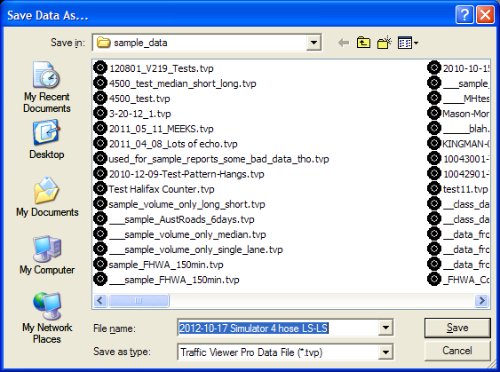
Make the filename something meaningful in case you need to retreive it later. The data will by default stored in the Data Directory specified in the Preferences.
Once the data has been successfully downloaded and configured you are ready to generate your reports of the data. To create a report click on the Print Reports button in the Data Overview panel.
If you are doing a speed/classify report, the following window will appear:
If you are doing a volume only report, there is only one report (the volume report) available, so no checkboxes will show on the right side of the window.
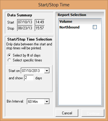
Data Summary should show the approximate start and stop date/time times for your study.
With Start/Stop Time Selection, specify the range of data to use in your report(s). Either by whole days, or the actual date/time start and date/time stop of data to use.
If you chose Select by # of days, then select a starting date from the Start on pull-down list and enter the number of days of data to show in the report in the and show -- days field. With this selection, all reports start at midnight of the first day and end at midnight of the last day.
If you chose Select specific times, the fields Start and Stop will appear in the panel so you may enter the start date/time, and the stop date/time.
Bin Interval is the count interval for the report. Most common is hourly data bins (60 Min). Care must be taken selecting the finer time resolutions since it can generate extremely large reports.
Once you have the report time range specified, then select the reports you wish generated from the checkboxs on the right side of the Start/Stop Time window. When you are ready, click on Continue to proceed to the Print Preview window.
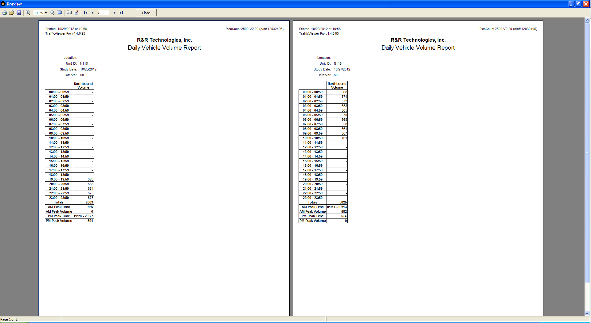
At this point, you can proceed to Print out the report or just Close the window to go back to the Data Overview panel. If you click on Print, a standard Windows® Print dialog will appear where you can select the printer you wish the report printed on and proceed to printing.
There are a variety of reasons that can result in count results not being what you expected. This chapter will discuss a variety of causes of unexpected results and how to remedy them.
These type of errors are mostly due to unfamiliarity with the hose setup options. Occasionally, even a seasoned operator can get caught by this when a normal default setting gets changed without being noticed. Generally, these errors are immediately detectable in the Data Overview Screen and are easily remedied by going back to the Data Settings screen and fixing the configuration. Sometimes the errors are subtle enough that they are not detected until the processed data is inspected. As mentioned throughout this manual, any time you download a count, be sure to save the data file first before creating any reports or exports, even if you are in a hurry, it only takes seconds.
This is one of the most common type of error that can happen which is caused by specifying the wrong hose connection, with the resulting data preview showing zero, or a very low counts. Simply clicking on Edit Header and correcting the hose to the proper channel will fix the problem. Often, an organization when doing single hose counts will specify that all single hose counts will be done with the A channel, which works most of the time, however, the operator might inadvertently connect it to one of the other channels instead, and not make a note of it. Nothing is lost, you just need to change channels to get your data. TrafficViewer Pro will often catch this condition and flash up a warning message.
This can be the result of several things.
The hose could become disconnected from the counter. Usually, the operator should note this when picking up the counter.
The hose comes loose from its anchor, and works its way to the edge of the roadway. Usually the operator should note this when picking up the counter.
The hose develops a tear or split. This would usually be on older hose. If the tear or split is small, the hose may count properly except when a vehicle tire strikes it just right, then not register counts. This may not be obvious to the operator and the bad hose may end up being used again and again before the tear becomes obvious. There is not much that can be done in this situation other than proper training so that the operators are aware that this condition can occur. The only surefire test of the hose that would detect this is a “pressure” test. For this test, you connect the hose up to a high pressure (say 40 to 100 PSI) through a gauge and a check-valve. Disconnect the pressure source and see if the hose holds the pressure.
The hose gets pinched shut. Sometimes when the operator is attaching the hose to the anchor on the counter end of the hose, the gripping device might pinch the hose shut. Maybe not right away, but with time. The symptom would be counts stopping after a period of time. This is a concern in hot weather when the hose becomes very soft. Again, operator awareness is the best remedy here.
In very hot climates, the rubber hose can become very soft and lose its springiness in the heat of the day, sometimes even sticking shut for periods of time. We recommend using “Heavy Duty” hose in these environments, it has far fewer issues of this type since the walls of the tubing are quite thick.
Stringing the hose across two or more lanes. In heavy traffic, you will have increasing odds of two tires in separate lanes striking the hose at near the same time appearing to be only one hit. This will cause the totals to be less than actual. This error can become significant (more than 5%) when per lane density is 1000 vehicles per hour.
This condition is the result of “noise” on the air hoses. In an ideal situation, when a tire squeezes the hose shut, it generates a single pulse of air. This air pulse travels down the hose at the speed of sound until it strikes the air hose switch, which is just a glorified microphone, which then records the hit. Unfortunately, this air pulse after striking the air switch heads back towards the tire and a complex resulting air pulse can be generated depending on hose lengths. In addition, the tire hit actually launches air pulses going both directions in the hose and when the tire leaves the hose, the air pulses going in the other direction, can now return back towards the air switch, contributing further to the air pulse complexity. Occasionally, when conditions are just right, these delayed air pulses can be strong enough to retrigger the air switch, giving a double or even triple count. The Dwell Time is used to filter out a lot of these issues. If your counts “seem” too high, you might try increasing the dwell time. You should see the counts drop off as you increase the dwell time, improving the high counts. At some point increasing the dwell time has little additional effect, that would probably be your best setting.
In addition to the issues above for single hoses, the most common error in this setup is reversing the long-hose and short-hose connections. TrafficViewer Pro will often detect this and flash up a warning message. This reversal is usually noticeable in the Data Overview window.
In addition to the single hose issues above, the most common error here is reversing the two hoses. This will generally be obvious from the Data Overview screen when you get zero or low counts. Another problem is when one of the channels is not collecting data, you can get what appears to be zero counts and reversing the hoses does not help. In this instance, speed and class data have not been collected because both hoses are necessary. However, all is not lost, you can get the volume only data from the one working hose.
The other problem is for very slow moving vehicles (under 20MPH), the noise issues mentioned above for the single hose can become very prominent. When this happens, your speed and classification data can get corrupted. We don’t recommend collecting speed and class at the lower speeds, however, you can possibly retrieve the data to an acceptable level by increasing the Dwell Time as described above. In these cases, very careful attention should be paid to laying the hoses in the lowest noise configuration possible.
This is not a recommended setup, however, in very low volume roadways (density of 100 vehicles per hour per lane), it can work quite effectively. If you are just after volume counts, the long hose - short hose configuration is far more accurate. For speed and class, just keep in mind the issues described above for single hoses across multiple lanes. Those same errors are multiplied for counts that must compute speed and class. Adjusting dwell times can help some of the noise issues, but nothing will help when two or more vehicles are crossing the hoses at the same time, the computing algorithms have a difficult time seperating the various hits into two vehicles. TrafficViewer Pro does have the ability to create your own classification schemes, and this issue can be improved somewhat by changing the “re-clustering” rules to maybe classify a non-classifyable cluster as (2) two axle vehicles.
Critical counts are considered counts that are for one time events, and/or for counts at remote locations where recounting is not an option.. Any count study can go bad for any of a number of reasons as discussed above. If you are going to be doing a critical count where re-counting is not a possibility, then you should take extra precautions when running the counts. Namely redundancy, or simultaneous duplicate counts. The extra cost for running the counts is nothing compared to losing a critical count.
The first line of defense is to run at least two separate counters for each desired count. In some circumstances if lots of counters are placed out for a study, covering all the exit and entry points to an event, it may be possible to reconstruct a missing counters data, but even this can be labor intensive.
If you are running single hose volume only counts, Consider running a second hose in the extra channel parallel to the first just for redundancy. If something happens to one hose the odds are the other hose will be okay.
In remote locations particularly, vandalism can be an issue. Here it would pay to place the second counter nowhere near the first counter.
Power: | |
Internal Battery: | 3.0Vdc Lithium type |
Battery Life: | 10 Years minimum |
Memory: | |
Memory Type: | Non-Volatile NAND Flash |
Memory Size: | 250 MegaBytes |
Data Retention: | 20 Years minimum |
Communications: | |
Type: | RS-232 ASCII Serial |
Data Frame: | 8 data bits, 1 stop, no parity |
Data Rates: | 115,200 Baud normal 921,600 Baud download |
Environmental: | |
Operating Temperature Range: | -40 F to +158 F -40 C to +70 C |
Relative Humidity: | 5 to 100% |
Water Resistance: | Can operate immersed in water |
RoHS Compliance: | Yes |
Physical: | |
Dimensions: | 4.00 x 2.00 x 0.90 inches 102 x 51 x 23 mm |
Weight: | 7 oz 200 grams |
Download Connector: | Conxall Mini-Con 4 pin circular |
Input Air Hose: | 3/16 - 1/4 inch ID 4.75 - 6.35 mm ID |
Enclosure Materials: | Gold anodized aluminum and stainless steel |
[a]Bill Rochat:
pictures???
[b]Bill Rochat:
pictures???
[c]Bill Rochat:
picture???
[d]Bill Rochat:
picture???
[e]Bill Rochat:
picture???
[f]Bill Rochat:
Perhaps describe the picture above... it's really two different setups, maybe split it too? So a newbie doesn't think setting out two counters separately is needed, or will accomplish anything.
[g]Bill Rochat:
Should we describe here how short/long works at all? Or just leave that alone?
[h]Bill Rochat:
maybe a photo?