CountBuddy II Manual
Last Updated 06/18/2015
Table of Contents
2.2.1.1 Hit Counts by Channel.
2.2.1.2 PicoCount Running Totals.
2.2.2.4 Show Information Item.
3.0 When Things Don't go Right.
3.1.1 The CountBuddy II is not Turning on.
3.1.2 After replacing the battery, the CountBuddy is dead.
3.1.3 Buttons are not responding.
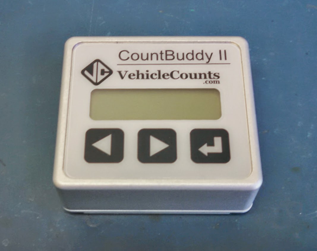
The VehicleCounts.com CountBuddy II is basically a hits verifier. It gives a live data view of hits on the PicoCount counters with a built-in LCD display. This unit is for verifying the hose connections and integrity when setting out PicoCount counters.
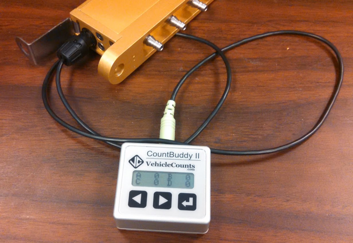
The CountBuddy II consists of two pieces: The display unit and a connecting cable. The connecting cable plugs into the display unit at one end and a PicoCount counter at the other. When the cable is plugged into a PicoCount counter, the display unit automatically “wakes up” and interrogates the counter. It will briefly display a sign-on message, then a connection message indicating the PicoCount type and firmware version. Then after a few more seconds the appropriate count totalizers will be displayed.
The unit is powered from a common CR2032 type of Lithium coin battery, available at most stores. The unit should operate at least 6 months on one battery with constant usage. There is a “CHANGE BATTERY” message that will “flash” on the top line of the display when it is time for a new battery.
The operations section of this manual walks through all the steps of operating your CountBuddy II. Each operation is described in some detail to help you understand normal usage.
Hit. When a moving vehicle tire strikes a hose generating an air pulse.
Hose. Specifically, the rubber air hose (pneumatic hose) used by the PicoCount for traffic sensing.
Roadway. The active surface of the highway, road, street, or driveway that vehicles travel on.
The following trademarks are used throughout this manual:
PicoCount is a trademark of R&R Technologies, Inc.
CountBuddy is a trademark of R&R Technologies, Inc.
TrafficViewer Pro is a trademark of R&R Technologies, Inc.
VehicleCounts.com is a trademark of R&R Technologies, Inc.
This section discusses the operation of the CountBuddy II.
The CountBuddy II has three different operating states:
1. Sleep: In this state, the display is off and the unit draws very little current from the battery.
2. Awake: In this state, the display is on, and will display hose hits when detected by the PicoCount counter.
3. Menus: In these states, the display is on, but the unit does not record any hits from the attached counter.
In addition, there is a backlight which can be useful in low light. The backlight can be toggled on and off by touching and holding the right button.
The unit will automatically enter the Sleep state when the CountBuddy II is unplugged from a PicoCount or there have been no hose hits for 5 minutes.
If the battery is low, the unit will “flash” the message “CHANGE BATTERY” in the Awake state. Also, when the battery is low, the backlight will not light, to preserve battery life as long as possible.
The CountBuddy II has three buttons directly below the display. These buttons are actually state-of-the-art electronic touch switches that sense your finger as it approaches the overlay. These switches do not need to be pushed, it is sufficient to only touch the overlay where the button is indicated. If a button does not seem to be responding simply pull your finger back and lightly re-touch the switch, applying pressure accomplishes nothing, and might degrade the instrument seals. Throughout this manual we state to “touch” the button, rather than “press” the button to emphasize that they only need to be lightly touched.
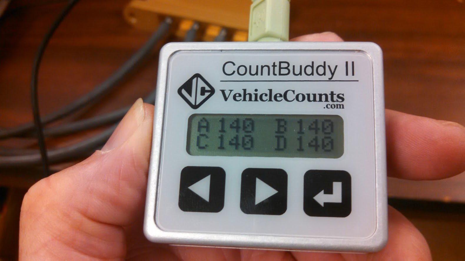
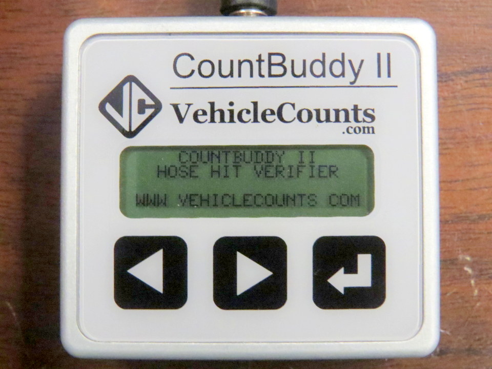
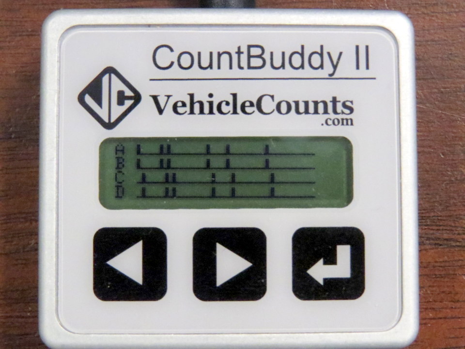
First, attach the counter interface cable to the CountBuddy II. Note, you may see the sign-on message displayed when you do this, but it should go out in 2 seconds. Then connect the other end of the cable to your PicoCount counter. You will see the sign-on message briefly followed by the ID screen indicating the type of PicoCount you are connected to and the firmware version running on the PicoCount, followed by the main screen. If you are connecting to a two channel counter, only two hit totalizers will show, otherwise four hit totalizers will show.
Upon waking up the CountBuddy II by connecting it to a PicoCount counter you should see something like:
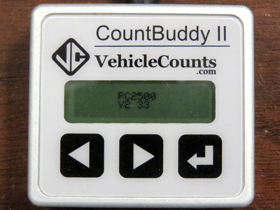
This screen will display for about 2 seconds, then you should see something like:
In this example it shows we have connected to a PicoCount 2500 unit running V2.33 firmware. This screen will display for about 5 seconds, then you should see something like:
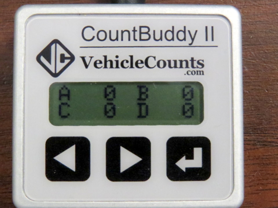
Or if connecting to a PicoCount 4500 four channel counter.
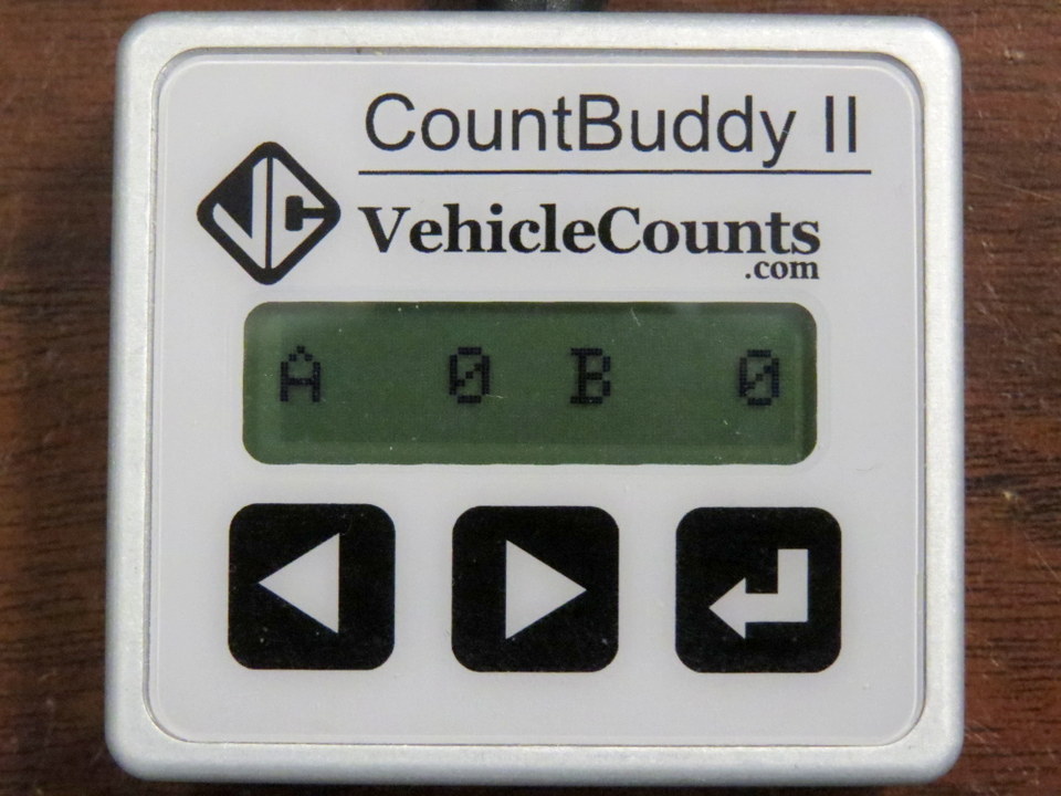
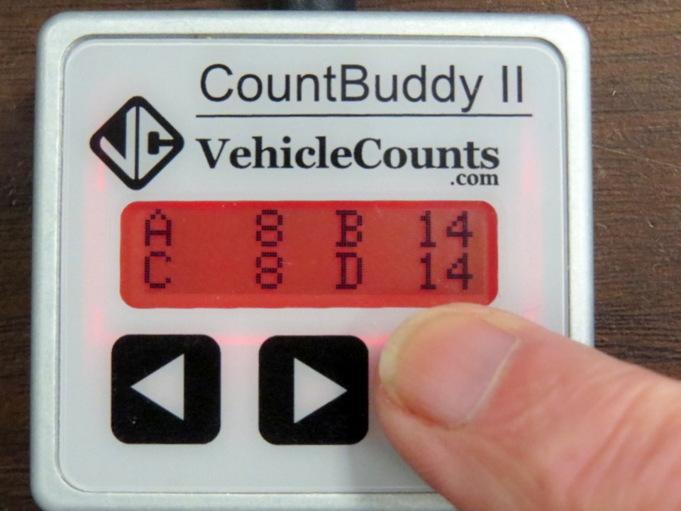
The display shows the counter channel followed by the hit total for that channel. The PicoCount 2500 has two channels A and B. The PicoCount 4500 has four channels A,B,C and D. The hit totals go from 0 to 999 then roll over to start at zero again. The hit counts are zeroed each time the cable is unplugged and re-attached, or if you access any of the menus and return to this screen.
The CountBuddy II has an LCD for displaying hose hits and 3 electronic “Touch” buttons. The CountBuddy II has a menu system built in to display additional information and perform other tasks. The three touch buttons on the unit do not need to be “pressed”, there is nothing that moves; they detect your finger presence as soon as you touch the panel. These buttons will not work well if you are wearing gloves, or if the panel gets standing water on it.
The CountBuddy II has several of operations, accessed with the three buttons across the bottom. A description of these operations follows. The operations are organized into three groups, the data displays group, the menu group, and the backlight.
The left button and the middle button are for scrolling through the groups. The left button goes to the “previous” item in a group and the middle button goes to the “next” item in a group.
The right button is used to toggle the backlight, to switch to the menu group, or to return to the main group.
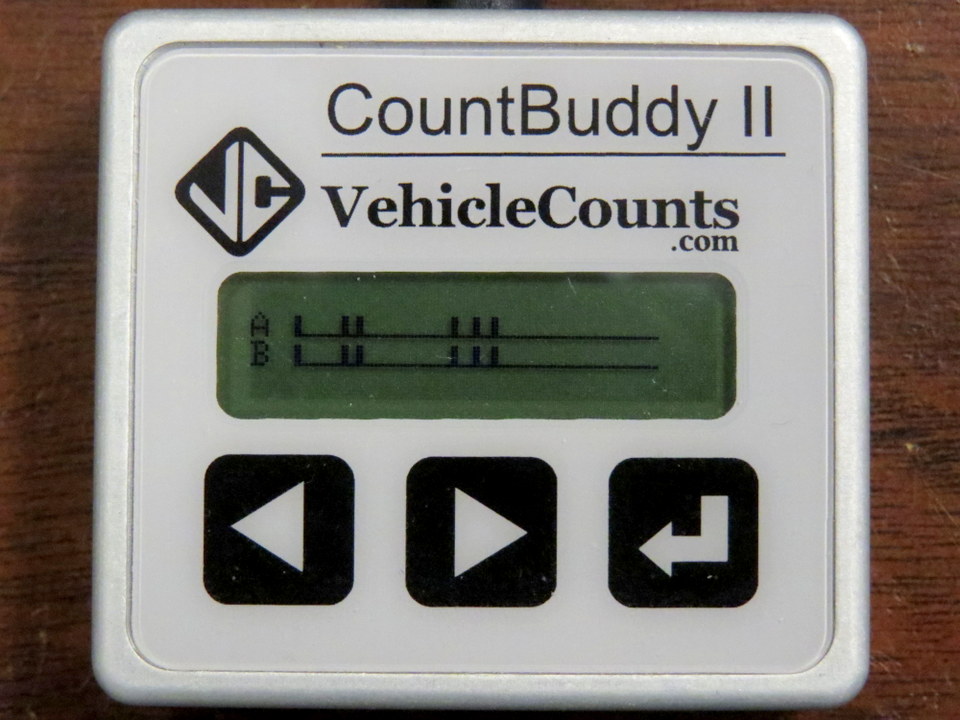
The data display group of screens consists of three modes of looking at hit data. The hit counts by channel, the hits in a graphical screen, and the PicoCount running totals. In each of these screens, the right button will switch to the menu with a quick touch, or toggle the backlight on and off with long presses.
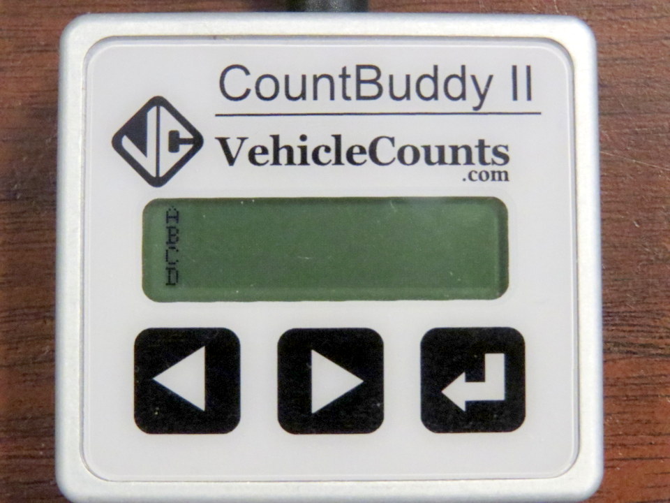
When you first connect the CountBuddy II to a PicoCount counter, it will come up in the hit counts by channel screen. This screen will either show two channels of hit counts or 4 channels of hit counts depending on which type of PicoCount counter it is attached to. Each time there is a hit in one of the channels, that channel’s count will be incremented. Each count goes from zero to 999. If the count goes over 999, then the count begins at zero again. Any time you leave this screen by the scroll buttons or by entering the menu group, when you return to this screen, the counts will be all set back to zero.
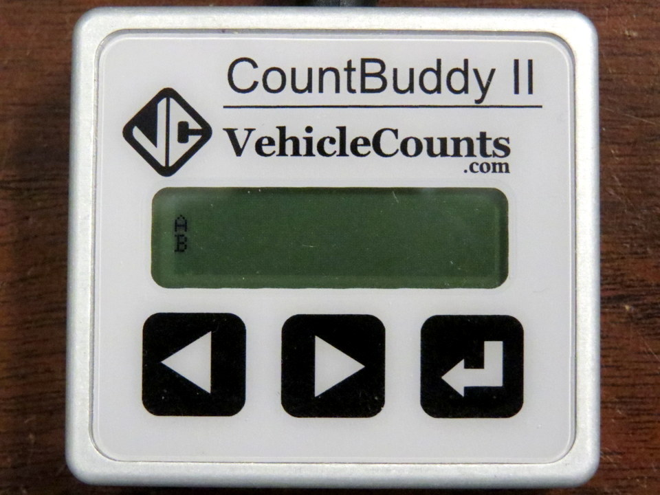
When you first enter the screen it will look like:
This screen will show the hose hits in real time.
When the first hose is struck, a graphical sweep will start showing the timing of each hit with respect to the first hit. This screen is most useful for spotting missing hits or extra hits on the hoses. Missing hits are a problem and should be resolved before leaving the counter to collect data. Extra hits may be unavoidable in some hose setups, but using this screen you can possibly minimize the extra hits. Generally our TrafficViewer Pro software will remove the extra hits with proper setting of the dwell time. The sweep takes a little less than two seconds, and after at least one second of delay, a new sweep can start. The new sweep will not start until a hose hit is detected.
or
When this screen is scrolled to, it displays the current running totals counters in the connected PicoCount counter. These counters are zeroed when the PicoCount counter has its data cleared, or when a new study is started, and they count every hit on each hose. These totals are useful when you are checking on a counter: At the start of a study you would normally expect only a few counts, possibly none, assuring you that the counter was properly cleared. During the study it can give you a very rough idea on whether the count session is running smoothly. If you were doing speeds and/or classifications, you would expect the two hoses doing this would have approximately the same counts. If there was a large difference, it could indicate a problem with the collection.
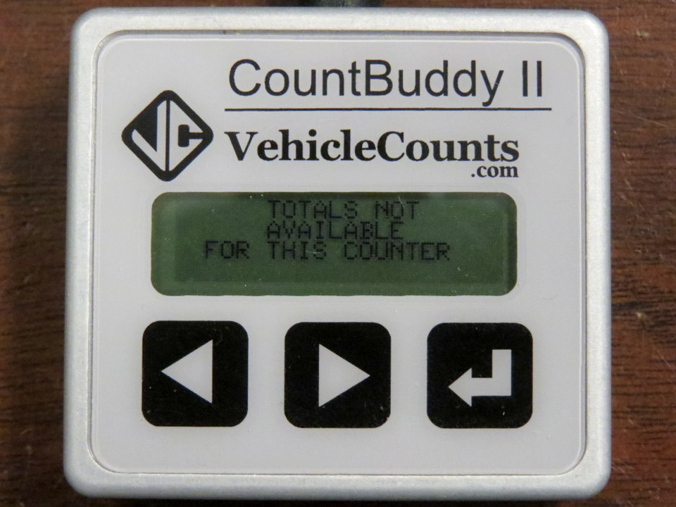
The hit totalizers are currently not implemented in the PicoCount counters, but will be very soon. If a counter you are connected to does not have these totalizers then you will see the following screen:
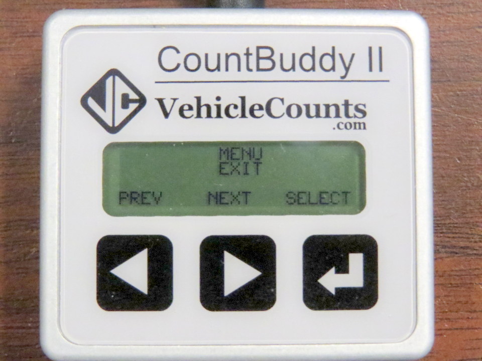
The menu group of screens consists of four tasks: The Exit item, the Start study item, the Stop Study item, and the Information item. In each of these screens, the right button will execute the task and then switch back to the main data display screen. The left and middle buttons will scroll through the menu items.
Upon entering the menu from the data display screens, this is the screen that will show. If you did not mean to enter the menu, you can just touch the right hand (select) button again to select “Exit” which will put you back to the main data display screen. Notice that the hit counts have been zero’d. This is a quick way of zeroing the hit counts.
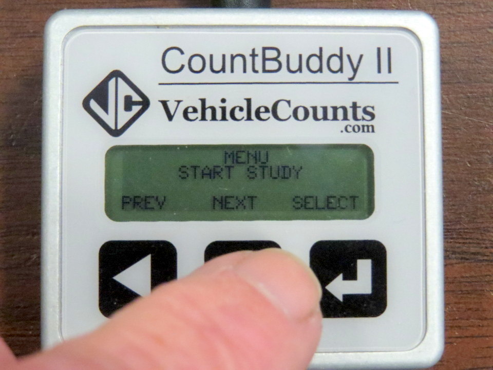
This menu item if selected will place a special timestamp in the PicoCount counter to indicate the beginning of a study. This feature is being implemented to support multiple studies in the PicoCount counters, which will be available soon.
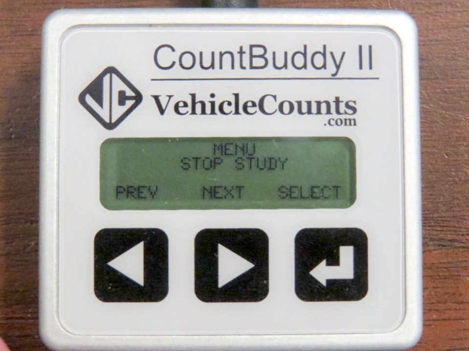
This menu item if selected will place a special timestamp in the PicoCount counter to indicate the end of a study. This feature is being implemented to support multiple studies in the PicoCount counters, which will be available soon.
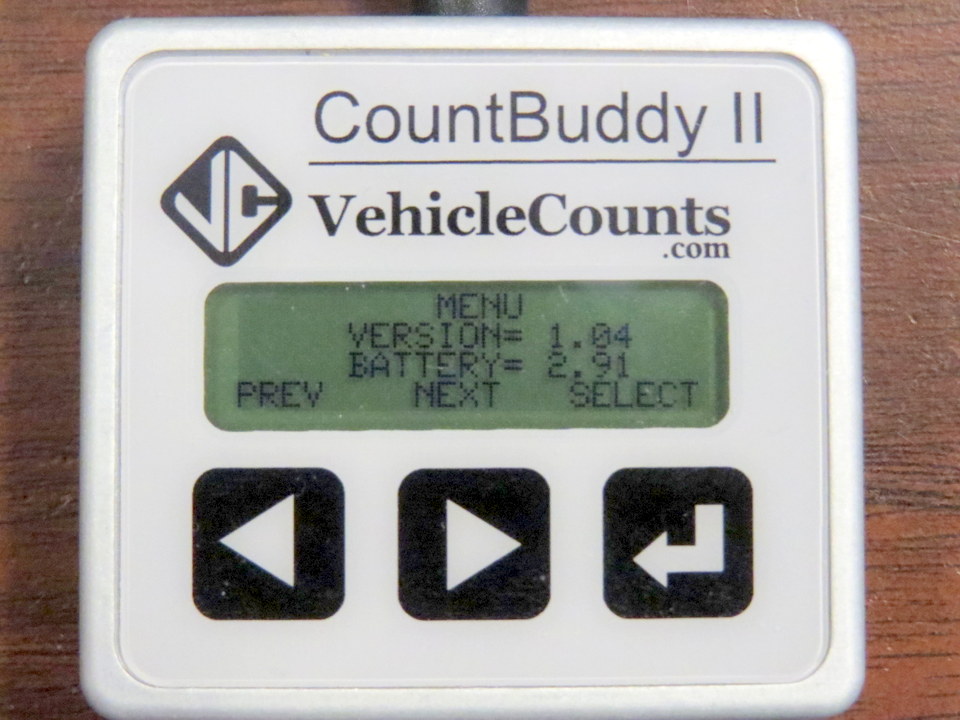
This menu item displays the current firmware (software) version in the CountBuddy II unit, as well as the battery voltage. For normal operations, the battery voltage should be 2.70 or more.
If it is getting dark, then the display can become very difficult to see. For those moments, there is a Backlight available. Use the backlight sparingly, it can have a dramatic affect on battery life.
While on the main data display screen, touch and hold the right button for about 2 seconds. This will turn the backlight on, or if it is already on this will turn it off. When you do not need the backlight any longer, you should turn it off. The backlight will also go off the moment you unplug the CountBuddy II from the PicoCount.
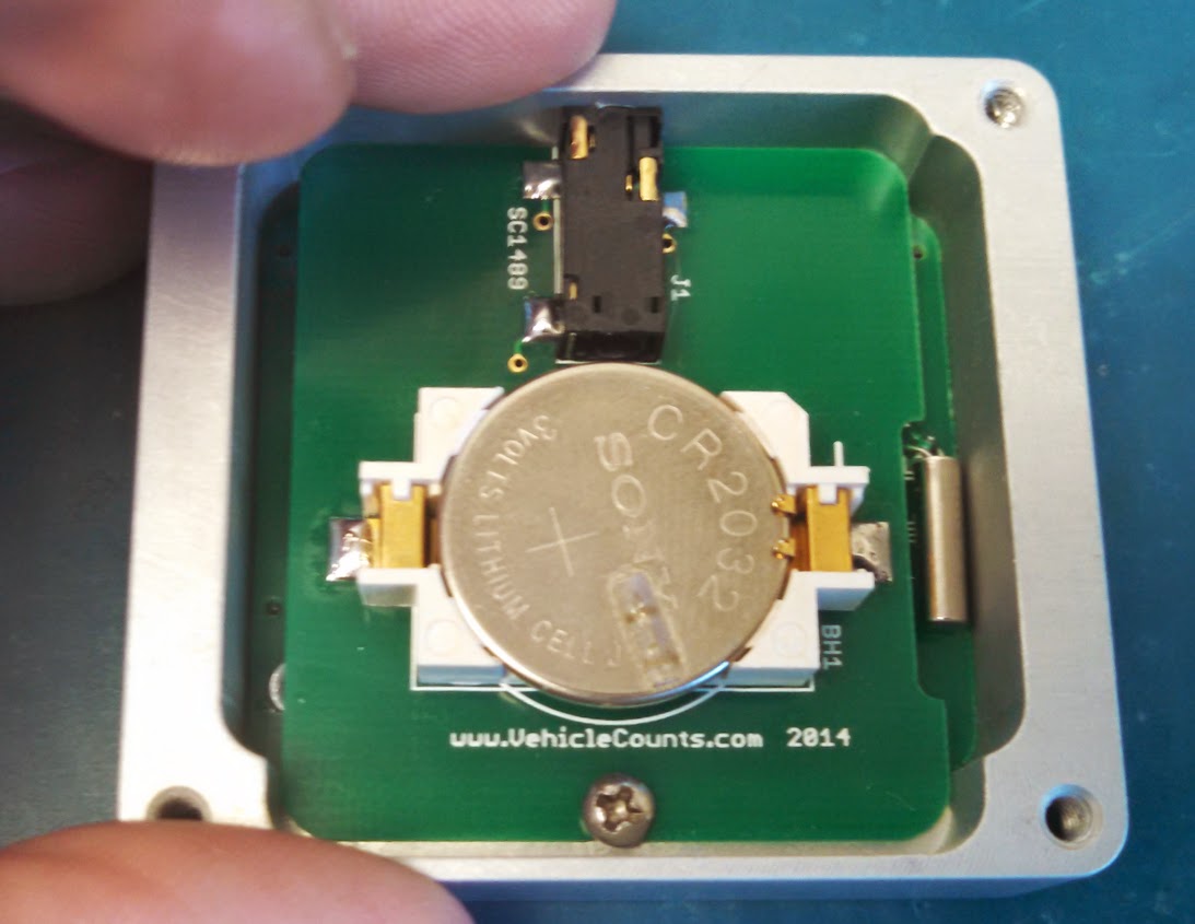
The CountBuddy II operates off of a single CR2032 type Lithium coin cell battery (sometimes called DL2032). This battery type is very popular and can be purchased nearly anywhere batteries are sold. These batteries are made by Energizer, Duracell, Sony, Maxell, Phillips, and Panasonic. This battery should give you at least 6 months of operation with heavy usage, and even more with light usage.
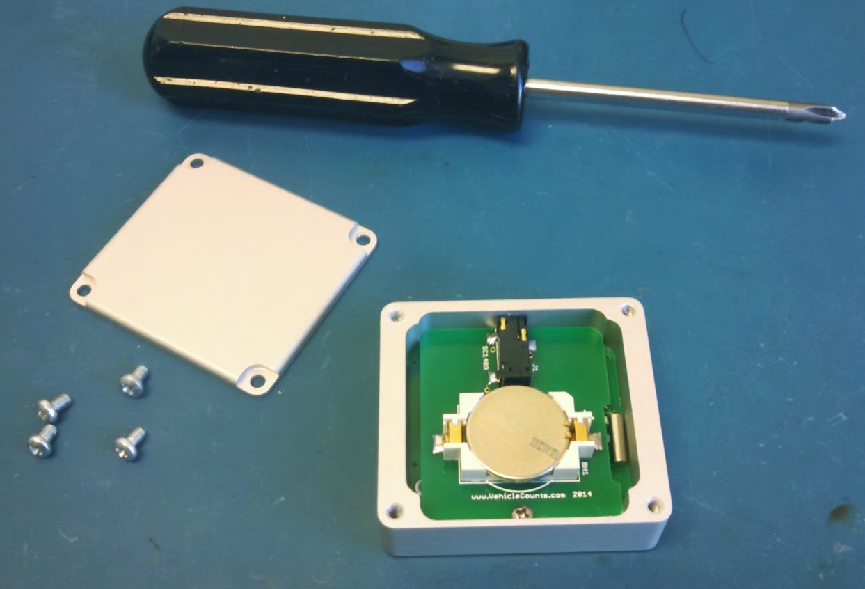
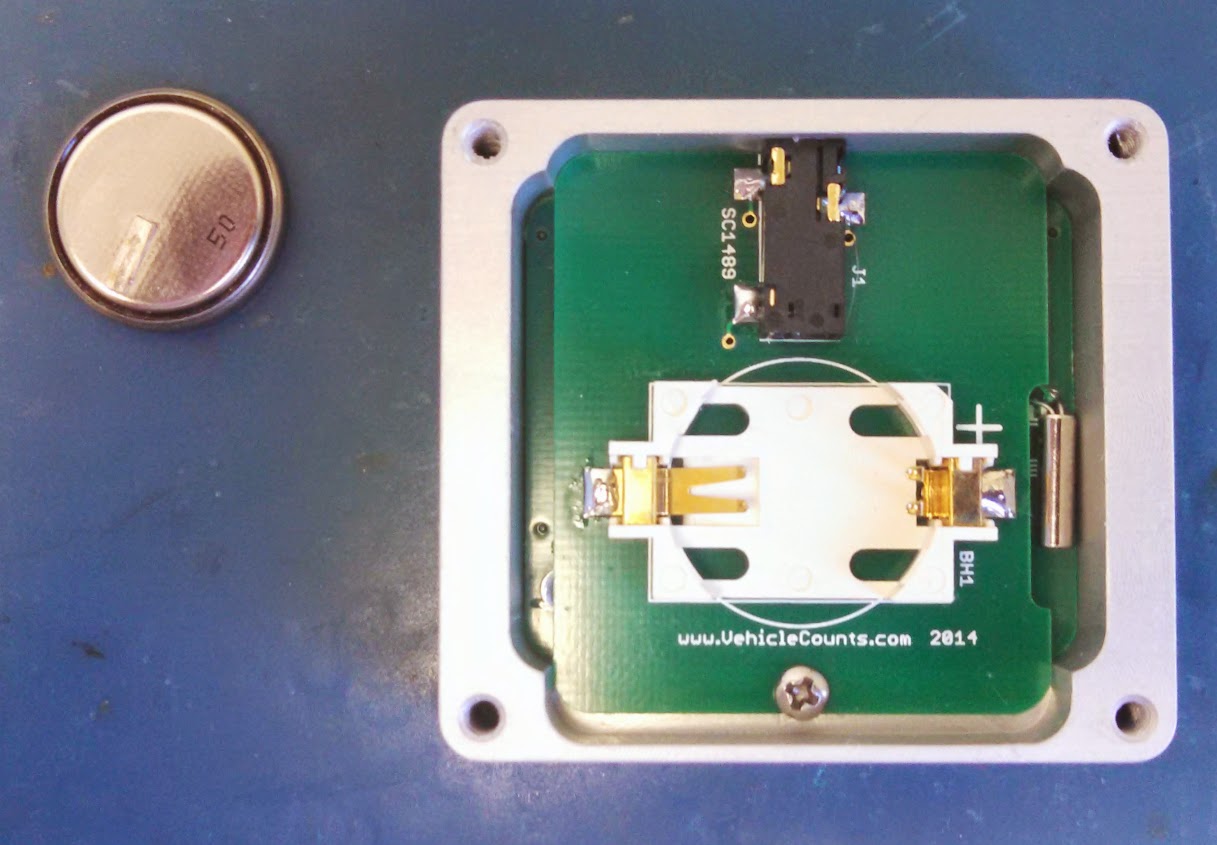
To replace the battery you will need a “Phillips” type screwdriver to open the battery cover. Perform this operation in a clean dry environment.
1. Remove the 4 screws on the battery cover with the Phillips screwdriver.
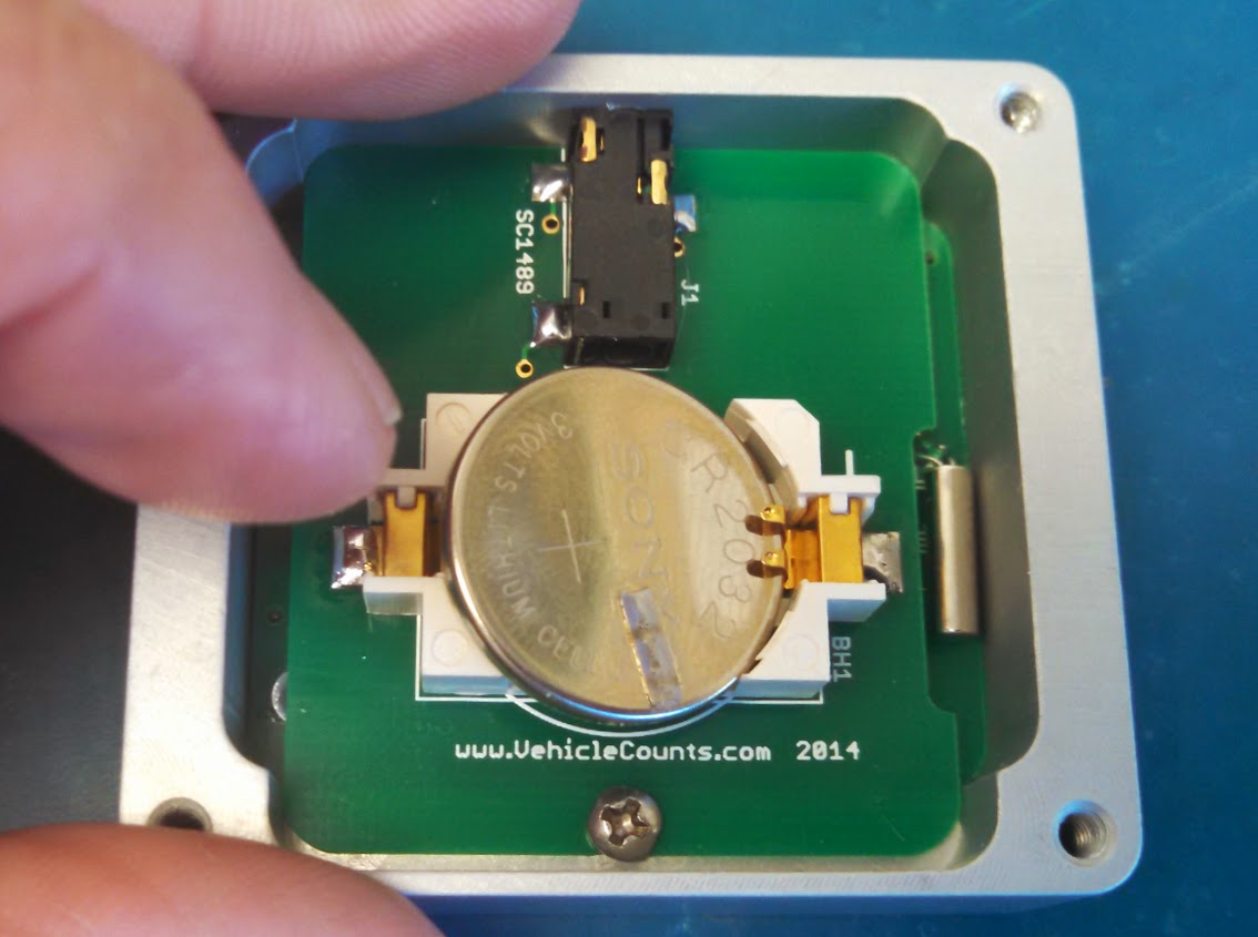
2. Notice how the battery is oriented in its holder with the “+” sign visible.
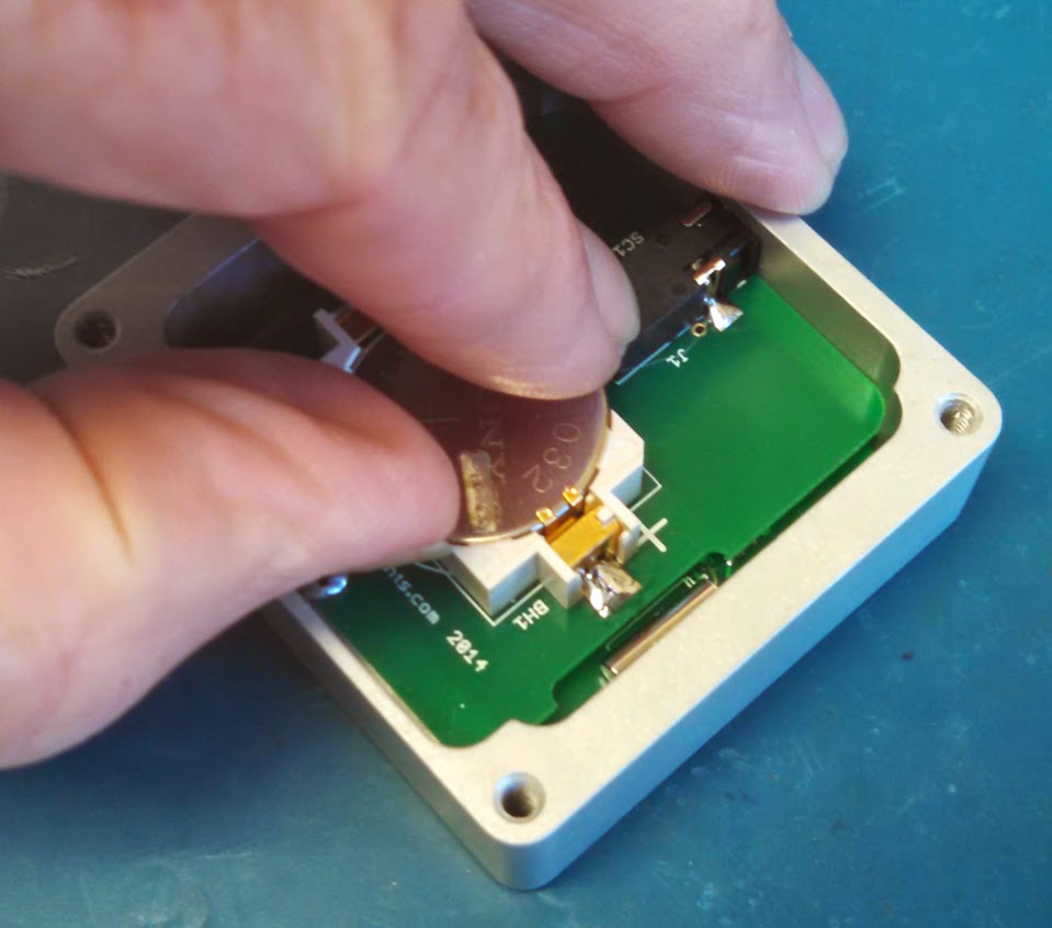
3. With your thumb, pry the battery out of the holder by lifting straight up.
4. Slide the new battery into the holder with one side under the small metal tabs, the “+” sign on the battery should be facing up.
5. Press the battery into place. You might hear a little “click” as it seats. In any case visually check that it is properly seated (flat and just barely below the lip of the holder).
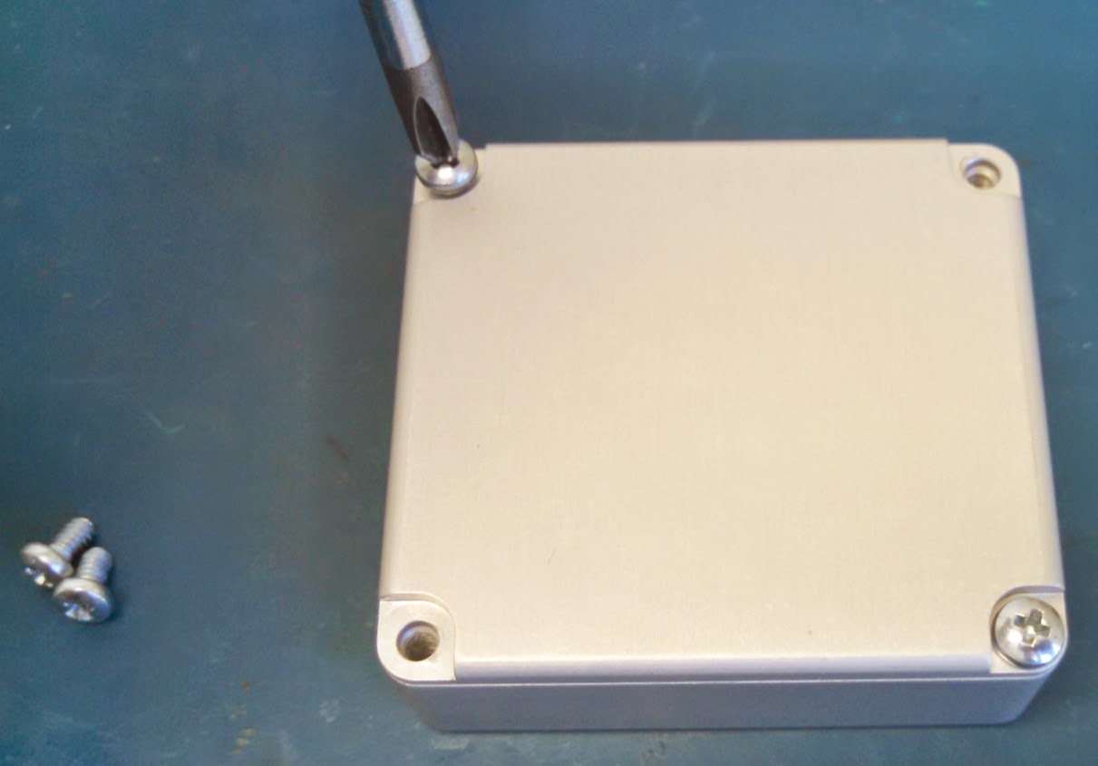
6. Flip the CountBuddy II over and observe that the display shows the sign-on message when attaching or removing the connecting cable.
7. If all is well, replace the battery cover and screws. Make sure you tighten the screws sufficiently.
There are a variety of reasons that can result in count results not being what you expected. This chapter will discuss a variety of causes of unexpected results and how to remedy them.
This is a list of issues that might pop up when using the CountBuddy II.
The CountBuddy II only turns on when it is connected to a PicoCount counter, otherwise it is always asleep. When the unit is sleeping, the buttons are not active and the unit will seem dead. If you connect the CountBuddy II to a PicoCount counter and it still shows no response, then the battery may be bad. Acquire a 2032 type battery from your local market and follow the instructions above to remove the old battery and install the new one.
If the CountBuddy II was working before you changed the battery and now it is not working, open the unit up and inspect the battery installation carefully (see pictures above). One issue we saw was that when installing the new battery, the user trapped the + fingers under the battery, instead of over the battery. If this happens, you can remove the battery and carefully, straighten up the pins, then insert the battery properly and it should work. The other issue that could occur is that the battery could be mounted upside down. Make sure that the (+) plus symbol on the battery is facing up when you install the battery.
If the touch buttons are not responding to touch, but the screen seems okay, unplug the PicoCount counter and reconnect it. This should clear up the problem. Sometimes the touch button routines get a faulty value for a “touch”. If you are wearing gloves the buttons may not pick up your touch, try it without gloves. Also be sure there is no standing water on the surface of the unit.
If the unit powers up okay, but seems to be acting strangely, unplug it from the PicoCount counter and plug it back in. That should clear the problem. The touch switches may have gotten into a strange state, or the CountBuddy II may have failed to connect to the PicoCount counter correctly. Either issue should be fixed by disconnecting and reconnecting the PicoCount counter.
These type of errors are mostly due to setup problems or faulty hoses. Generally, these errors are immediately detectable when the first vehicles drive over the hoses and the expected hit counts are off.
This can be caused by a few conditions. First verify that the hose connection is nice and firm. Next check the hose for pinch points (sometimes the grip is too tight and pinches the hose shut). If all seems okay, check the hose closely for a hole, tear, or split. If all still seems okay, then try to verify that the counter is working properly, by removing the hose and gently “puffing” into the nozzle with your mouth. If the problem persists, try another counter to verify if it is the counting setup or the counter that is faulty.
This can be the result of several things.
The hose develops a tear or split. This would usually be on older hose. If the tear or split is small, the hose may count properly except when a vehicle tire strikes it just right, then not register counts.
The hose gets pinched shut. Sometimes when the operator is attaching the hose to the anchor on the counter end of the hose, the gripping device might pinch the hose shut. Maybe not right away, but with time. The symptom would be counts stopping after a period of time. This is a concern in hot weather when the hose becomes very soft.
Stringing the hose across two or more lanes. In heavy traffic, you will have increasing odds of two tires in separate lanes striking the hose at near the same time appearing to be only one hit. This will cause the totals to be less than actual. This error can become significant (more than 5%) when per lane density is 1000 vehicles per hour.
Long hose runs can cause low counts because the signal has become too weak to register all the time.
This condition is the result of extra pulses on the air hoses. When a tire squeezes the hose shut, it generates a pulse of air. This air pulse travels down the hose at the speed of sound (about 1130 feet per second) until it strikes the air hose switch, which then records the hit. This air pulse after striking the air switch then reflects back towards the tire and a complex resulting air pulse can be generated depending on hose lengths. Additionally, the tire hit actually launches air pulses going both directions in the hose and when the tire leaves the hose, the air pulses going in the other direction, can now return back towards the air switch, contributing further to the air pulse complexity. Occasionally, when conditions are just right, these delayed air pulses can be strong enough to retrigger the air switch, giving double or even triple counts.
Power: | |
Internal Battery: | 3.0Vdc Lithium type CR2032 |
Battery Life: | 6 months typical |
Display: Type: Displayed Counts: Maximum Count: | LCD with backlight 2 or 4 channels 999 hose hits per channel |
Environmental: | |
Operating Temperature Range: | -4 F to +158 F -20 C to +70 C |
Relative Humidity: | 5 to 100% |
Water Resistance: | Yes |
Physical: | |
Dimensions: | 2.10 x 1.90 x 0.75 inches 54 x 48 x 19 mm |
Weight: | 2.7 oz 74 grams |
Input Connection: | Stereo Jack type 3.5mm |
Enclosure Materials: | Anodized Aluminum, Stainless Steel, and Lexan. |