Road Tube Simulator MANUAL
December 6, 2011
VehicleCounts.com Copyright 2011
TABLE OF CONTENTS
SECTION 1 -- INTRODUCTION
SECTION 2 -- OPERATING PROCEDURES
2.1 Unpacking your Road Tube Simulator
2.2 Getting familiar with the Road Tube Simulator
2.3 Let’s power up the Road Tube Simulator
2.4 Operating modes of the Road Tube Simulator
2.4.1.1 The stopped mode screen
2.4.1.2 The buttons in stopped mode
2.4.2.1 The running mode screen
2.4.2.2 The buttons in running mode
2.4.3.1 The buttons in menu mode
2.5.4 Pattern #4: 2-way counts
2.5.5 Pattern #5: 2-way speeds
2.5.6 Pattern #6: 2-way classes
2.5.7 Pattern #7: 4 channel long-short counts
2.5.8 Pattern #8: 4 channel long-short speeds
2.5.9 Pattern #9: 4 channel long-short classes
2.5.10 Pattern #10: 4 channel 2-way long-short counts
2.5.11 Pattern #11: 4 channel 2-way long-short speeds
2.5.12 Pattern #12: 4 channel 2-way long-short classes
2.6 Using the Road Tube Simulator to test air switches
SECTION 3 -- APPENDICES
3.1 Upgrading your Road Tube Simulator firmware
3.2 Installing USB drivers for your Road Tube Simulator
SECTION 1
INTRODUCTION
1.1 The Road Tube Simulator
The VehicleCounts.com Road Tube Simulator is a precision 8 channel traffic simulator that generates air pulses similar to the pulses coming out of air hoses installed on the street.
The simulator can be used to verify and certify the operation of all brands of air hose driven counters, speed analyzers, or classifiers. This unit has a two line OLED display which is used to configure the simulator and to display various parameters while running, such as accumulated vehicle counts.
With it’s adjustable air pulse output amplitude, air switch operation can be verified over a wide range of pulse amplitudes. This makes it possible to detect air switches that are deteriorating with time, or that are getting plugged with road debris.
The Simulator generates pairs of air pulses in a variety of patterns to calibrate up to 4 two channel counters or two 4 channel counters.
There are 12 selectable traffic patterns to choose from: Six two channel patterns and Six four channel patterns for long hose-short hose simulations.
Hose spacing for the tests can also be selected from 2 feet to 16 feet.
The Road Tube Simulator also has a USB connection to allow upgrading the firmware to the latest available through VehicleCounts.com’s TrafficViewer Pro software (version 1.3.1.82 or higher).
SECTION 2
OPERATING PROCEDURES
2.1 Unpacking your Road Tube Simulator
Carefully unpack your order, you should have received the Road Tube Simulator unit, a 24 Vdc wall transformer, and eight 18 inch hoses. If there are any discrepancies, notify VehicleCounts.com immediately.
After unwrapping your Road Tube Simulator, visually inspect it for any obvious physical damage that may have occurred while in shipment.
2.2 Getting familiar with the Road Tube Simulator
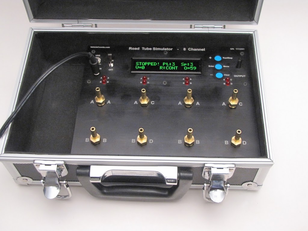
First lets look over the front panel to become familiar with the various features and controls.
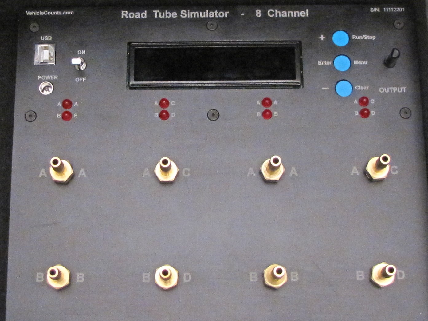
Starting in the upper left hand part of the panel is a USB connector used for upgrading the Road Tube Simulator firmware. Just below that is the power jack that the wall transformer plugs into to power the Simulator. Just to the right of that is a toggle switch to turn power on and off. In the upper middle of the panel is a two line OLED display with 20 characters per line. Just to the right of the display are three push buttons which are used to configure and operate the Simulator. To the right of these is a knob labeled “OUTPUT”. This knob sets the amplitude of the air pulses being generated by the Simulator.
Below the display are 8 LEDs which flash each time an air pulse is generated on the corresponding output. These indicators are labelled on the left with A and B for two hose configurations, and on the right with A,B,C and D for four hose configurations.
Below the LEDs are 8 output nozzles. These are where the air pulses come out. These nozzles are standard ⅛ NPT fittings. These nozzles are labelled on the left with A and B for two hose configurations, and on the right with A,B,C and D for four hose configurations.
2.3 Let’s power up the Road Tube Simulator
Make sure that the power switch is in the “off” position. Plug the supplied wall mount transformer into a power outlet, then attach the end of the cable to the Simulator. The power jack for the Simulator is on the upper left hand side of the panel.
Flip the power switch to “on”.
The display should light up with a sign-on screen for a few seconds:
VehicleCounts.com RT Simulator-8 V1.01 |
If the display does not light, make sure the wall transformer is plugged into an active wall outlet and firmly seated into the power jack on the Simulator panel.
Then switch to the “Stopped” screen like below:
STOPPED! Pt:1 Sp:4 V=0 R:CONT O=15 |
Notice the screen says “Stopped!” in the upper left.
At this point if you press the “Run/Stop” switch (upper switch on right hand side of display), you will see the screen say “Running!” in the upper left. You should also notice the LEDs flashing and hear clicking sounds coming from the outputs. If the LEDs are flashing but there is no clicking, turn the Output knob clockwise. You will notice that on the lower left part of the display screen you will see something like “O=15”. This is the output amplitude (or volume), it will vary from O=0 to O=99 as you turn the Output knob clockwise.
Congratulations! You have an operating Simulator. Below, we discuss in detail the operation of the Road Tube Simulator.
2.4 Operating modes of the Road Tube Simulator
The Road Tube Simulator has three operating modes: Stopped, Running, and Menus.
2.4.1 Stopped mode
The Stopped mode is the mode the Road Tube Simulator is in at power on. In this mode you can review the Simulator configuration, go to the Running mode, go to the Menu mode, clear the totalizers and set the Output amplitude.
2.4.1.1 The stopped mode screen
First, lets dissect the data showing on the screen:
STOPPED! Pt:1 Sp:4 V=0 R:CONT O=15 |
Starting on the upper line at the left, “Stopped!” indicates that we are in the Stopped mode.
Going to the right, the “Pt:1” indicates which test pattern will be used.
Going to the right, the “Sp:4” indicates the hose spacing in feet that will be simulated.
On the lower line left side “V=0” is a counter that indicates how many vehicles have been generated by the Road Tube Simulator while it was in the Running mode.
Going to the right, the “R:CONT” indicates how long or for how many vehicles the Road Tube Simulator is to stay in the Run-Start mode. In this case, the CONT stands for continuous, the Road Tube Simulator will run continuously until it is stopped by pressing the Run/Stop button.
Going to the right, the “O=15” is the current setting of the Output knob. If you move the knob, you will see this value move up and down from 0 to 99.
2.4.1.2 The buttons in stopped mode
The three buttons to the right of the display in Stopped mode are labelled from top to bottom, “Run/Stop”, “Menu”, “Clear”.
Pressing the “Run/Stop” button will switch to the Running mode and begin the vehicle simulations by the Simulator. You will see the “Stopped!” change to “Running!”. This mode will be discussed below.
Pressing the “Menu” button will switch to the Menu mode. You will see the screen saying “Select Task: Quit”. This mode will be discussed below.
Pressing the “Clear” button will clear the vehicle and axle counters. When you switch to the Running mode, these two counters will begin accumulating counts. When you switch back to Stopped these two counters will be frozen at the last accumulated count. If you go back to Running mode, it will continue to add to the counters.
2.4.2 Running mode
The Running mode is the vehicle simulating mode of the Road Tube Simulator. In this mode you can go to the Stopped mode, and set the Output amplitude.
2.4.2.1 The running mode screen
RUNNING! Pt:1 Sp:4 V=14 R:CONT O=37 |
This screen is nearly identical to the Stopped screen described above.
Starting on the upper line at the left, “Running!” indicates that we are in the Running mode.
Going to the right, the “Pt:1” indicates which test pattern we are using.
Going to the right, the “Sp:4” indicates the hose spacing in feet that we are simulating.
On the lower line left side “V=14” is a counter that indicates how many vehicles have been generated by the Road Tube Simulator so far, it will increment each time another vehicle is simulated.
Going to the right, the “R:CONT” indicates how long or for how many vehicles the Road Tube Simulator is to stay in the Run-Start mode. In this case, the CONT stands for continuous, the Road Tube Simulator will run continuously until it is stopped by pressing the Run/Stop button.
Going to the right, the “O=37” is the current setting of the Output knob. If you move the knob, you will see this value move up and down from 0 to 99.
2.4.2.2 The buttons in running mode
The three buttons to the right of the display in Running mode are labelled from top to bottom, “Run/Stop”, “Menu”, “Clear”.
Only the “Run/Stop” button is active and will switch the Road Tube Simulator to the Stopped mode.
2.4.3 Menu mode
The Menu mode in conjunction with the three buttons to the right of the display allow you to change the configuration of the Road Tube Simulator, and return to the Stopped mode.
2.4.3.1 The buttons in menu mode
The three buttons to the right of the display in Menu mode are labelled from top to bottom, “+”, “Enter”, “-”.
All the menu items are either task lists or selection lists.
The “+” button increments a task or value.
The “Enter” button selects the task or value currently displayed.
The “-” button decrements a task or value.
If you press the “+” key enough times, it will reach the top of the list, then wrap around to the bottom of the list and continue up.
If you press the “-” key enough times, it will reach the bottom of the list, then wrap around to the top of the list and continue down.
2.4.3.2 The main menu
When you first enter Menu mode, you will see the following screen:
SELECT TASK: QUIT
|
If you press the “Enter” button, you will return to the Stopped mode.
If you press the “+” or “-” button, you will increment or decrement to the next task on the list.
Currently there are four tasks: Quit, Pattern, Run-time and Spacing. Pressing “Enter” while pointing to “Quit” will return you to the Stopped mode.
SELECT TASK: PATTERN
|
SELECT TASK: SPACING
|
SELECT TASK: RUNTIME
|
2.4.3.3 The pattern list
SELECT PATTERN: 1
|
In this screen you can cycle through all the available patterns. Currently there are 12 patterns to choose from 1 to 12. When you have incremented or decremented to the desired pattern, press the “Enter” button to select the value. You will then be sent back to the Main Menu, where you can select another task, or return to the Stopped mode. The value you selected will be permanently remembered by the Simulator until you change to another pattern. Your newly selected pattern will be shown on the Stopped and Running screens.
A brief description of the 12 patterns are as follows, currently all patterns are 15 vehicles long, and cycle continuously until stopped. Details on each pattern are listed later in this manual.
Pattern 1: “COUNTS” A two axle class two vehicle traveling at 35MPH, ..repeated 15 times with 2 second pacing (a new vehicle is generated each 2 seconds).
Pattern 2: “SPEEDS” A two axle class two vehicle traveling at 12MPH, 17MPH, 22MPH …. 72MPH with 4 second pacing.
Pattern 3: “CLASSES” One each of the 13 FHWA vehicle classifications plus one extra class 2 and class 3 vehicle, traveling at 35MPH with a 4 second pacing.
Patterns 4, 5, and 6 are bi-directional versions of patterns 1,2, and 3. Where each vehicle is presented going forwards, then backwards, giving an effective 30 vehicle pattern.
Patterns 7, 8, and 9 are 4 channel long-hose/short-hose versions of patterns 1, 2, and 3 with each vehicle simulated in two lanes traveling in the same direction. With an effective 30 vehicle pattern.
Patterns 10, 11, and 12 are 4 channel long-hose/short-hose versions of patterns 1, 2, and 3 with each vehicle traveling in two lanes in opposite directions. With an effective 30 vehicle pattern.
2.4.3.4 The spacing list
SELECT SPACING: 4
|
In this screen you can cycle through all the available hose spacings. Currently there are 15 hose spacings to choose from 2 to 16 feet. When you have incremented or decremented to the desired spacing, press the “Enter” button to select the value. You will then be sent back to the Main Menu, where you can select another task, or return to the Stopped mode. The value you selected will be permanently remembered by the Simulator until you change to another spacing. Your newly selected spacing will be shown on the Stopped and Running screens.
2.4.3.5 The runtime list
SELECT RUN-TIME: CONTINUOUSLY |
In this screen you can cycle through the available run-time options. Currently there are 10 run-time settings to choose from, these are listed below. When you have incremented or decremented to the desired run-time, press the “Enter” button to select the value. For all run-time options except “Continuously”, when the run-time is finished, the Road Tube Simulator will automatically return to the Stopped mode.
1. Continuously
2. 1 Minute
3, 5 Minutes
4. 15 Minutes
5. 1 Hour
6. 24 Hours
7. 100 Vehicles
8. 500 Vehicles
9. 1000 Vehicles
10. 5000 Vehicles
2.5 The test patterns
The Road Tube Simulator generates 3 base patterns (counts, speeds, classes) and 9 derived patterns. These patterns will allow you to test virtually all two and four channel air hose counters, speed analyzers, and classifiers in the industry. The paragraphs below go into detail on each of the generated patterns.
2.5.1 Pattern #1: Counts
Counts: Simulates a two axle vehicle with an 8 foot wheelbase traveling at precisely 35MPH. One vehicle is generated each two seconds. The A output leads the B output. This pattern would be used primarily to test and certify simple traffic counters and to test air switches (see below). This sequence repeats every 2 seconds.
To certify a counter, set the counter up for counting mode and the desired sampling interval (some counters do not require the sampling intervals to be set). Start the counter and the Simulator. Set the pulse output amplitude to well above the air switch threshold (see testing of air switches below), or at maximum.
In the case of interval counters, most do not begin sampling until the interval time begins, so make sure you allow the Simulator and counter to run at least twice as long as the interval. Once the intervals start, each interval should show exactly the same count as indicated in the table below.
In the case of time-stamping counters, the interval reports they generate should be precisely the same.
The counts generated by the A and B outputs would be as follows:
Interval | Output A | Output B |
5 Minute | 150 | 150 |
15 Minute | 450 | 450 |
1 Hour | 1800 | 1800 |
24 Hour | 43200 | 43200 |
Axle counts (pulses) would be exactly twice the vehicle counts shown above.
In the case of simple totalizer counters, reset the counter’s count and the Simulators count at the same time, then run for the certification period. The two counts should be in exact agreement at all times if all is going well.
2.5.2 Pattern #2: Speeds
Speeds: Simulates a two axle vehicle with an 8 foot wheelbase traveling at 12MPH to 82MPH in 5MPH increments. One car is generated each 4 seconds with the A output leading the B output. This pattern would be used primarily to test and certify speed and classification traffic counters and, to a lesser extent, counters. This sequence repeats every minute.
To certify a counter, set the counter up for the mode to test and the desired sampling interval, if appropriate. Start the counter and the Simulator. Set the pulse output amplitude to maximum. Important Note: The A and B hoses must be the same length.
Caution needs to be exercised when using this mode since most air switches will not operate over the full range of speeds this mode generates. Some brands of air switches will not detect speeds above 60 to 65 MPH, and many switch types will not detect the 10 MPH consistently. The four second delay between vehicles is to allow the counters to clear vehicle detect if the air switches are beginning to fail.
The pattern generated is:
13, 17, 22, 27, 32, 37, 42, 47, 52, 57, 62, 67, 72, 77, and 82 MPH. One vehicle each four seconds, for a one minute repeating cycle.
The speeds are chosen to fall near the middle of the normal binning ranges 10 to 15, 15 to 20, etc.
In the case of time-stamp counters, the raw data reports should show the above pattern if the air switches can handle all of the speeds and the counter can resolve times close enough.
In the case of speed survey counters, set the headway time to the shortest time allowed, then the speed profiles should show counts in each of the speed categories above, however, depending on the headway times selected, the counts in each speed may differ. Again, if the air switches can’t properly respond to all speeds, those will not show.
In the case of classifying counters, set the interval to the desired value. The reports should show all vehicles as class 2 over the range of speeds indicated above, provided the air switches are up to the task.
In the case of interval counters, the following counts should accumulate for each interval if the air switches can operate over the whole range:
The counts generated by the A and B outputs would be as follows:
Interval | Output A | Output B |
5 Minute | 75 | 75 |
15 Minute | 225 | 225 |
1 Hour | 900 | 900 |
24 Hour | 21600 | 21600 |
2.5.3 Pattern #3: Classes
Classes: Simulates each of the 13 FHWA classes with the vehicles traveling at precisely 35MPH. One vehicle is generated each 4 seconds in a repeating pattern. Each pattern generates 15 vehicles (class 2 and class 3 are generated twice) and 54 axles. The A output leads the B output. This pattern would be used primarily to test and certify classification traffic counters. This sequence repeats every minute.
Important Note: The A and B hoses must be the same length.
The pattern generated is:
Vehicle | FHWA Class | Axles | Axle Spacings (feet) | Run Length (feet) |
1 | 1 | 2 | 5 | 5 |
2 | 2 | 2 | 7 | 7 |
3 | 2 | 2 | 9 | 9 |
4 | 3 | 2 | 11 | 11 |
5 | 3 | 2 | 12 | 12 |
6 | 4 | 2 | 30 | 30 |
7 | 5 | 2 | 18 | 18 |
8 | 6 | 3 | 15, 4 | 15, 19 |
9 | 7 | 4 | 18, 4, 4 | 18, 22, 26 |
10 | 8 | 4 | 10, 25, 4 | 10, 35, 39 |
11 | 9 | 5 | 10, 4, 24, 5 | 10, 14, 38, 43 |
12 | 10 | 6 | 12, 4, 24, 5, 5 | 12, 16, 40, 45, 50 |
13 | 11 | 5 | 14, 20, 10 , 20 | 14, 34, 44, 64 |
14 | 12 | 6 | 12, 4, 20, 10, 20 | 12, 16, 36, 46, 66 |
15 | 13 | 7 | 13, 4, 20, 4, 20, 4 | 13, 17, 37, 41, 61, 65 |
To certify a counter, set the counter up for the mode to test and the desired sampling interval, if appropriate. Start the counter and the Simulator. Set the pulse output amplitude to maximum. Important Note: The A and B hoses must be the same length.
In the case of time-stamp counters, the raw data reports should show the above pattern
In the case of speed survey counters, set the headway time to the shortest time allowed, then the speed profiles should show counts in each of the speed categories above, however, depending on the headway times selected, the counts in each speed may differ.
In the case of classifying counters, set the interval to the desired value. The reports should show all vehicles as indicated in the table above, accumulating at 1 per minute (except class 2 and 3 which accumulate at 2 per minute).
2.5.4 Pattern #4: 2-way counts
Bi-directional Counts: Simulates a two axle vehicle with an 8 foot wheelbase traveling at precisely 35MPH. One vehicle is generated each two seconds. First a forward traveling vehicle is generated with the A output leading the B output. Then the same vehicle is generated traveling in the opposite direction with the B output leading the A output. This sequence repeats every 4 seconds.
2.5.5 Pattern #5: 2-way speeds
Bi-directional Speeds: Simulates a two axle vehicle with an 8 foot wheelbase traveling at 12MPH to 82MPH in 5MPH increments. One car is generated each 4 seconds with the first vehicle at each speed traveling in the forward direction, the A output leads the B output, and the second vehilce traveling in the opposite direction, the B output leads the A output.. This pattern would be used primarily to test and certify speed and classification traffic counters. This sequence repeats every 2 minutes.
2.5.6 Pattern #6: 2-way classes
Bi-directional Classes: Simulates each of the 13 FHWA classes with the vehicles traveling at precisely 35MPH. One vehicle is generated each 4 seconds in a repeating pattern. Each vehicle is first simulated going forward, the A output leads the B output, then in reverse, the B output leads the A output.. Each pattern generates 15 vehicles (class 2 and class 3 are generated twice) and 54 axles. This pattern would be used primarily to test and certify classification traffic counters. This sequence repeats every two minutes.
Each of the patterns above can be used with 2 channel or 4 channel counters. The patterns that follow are specifically for 4 channel counters configured with two channels of long hoses stretched across two lanes of traffic, and two channels of short hoses stretched across one lane only. This is a method that allows the counters to determine lane occupancy. The Road Tube Simulator does not allow the simulated vehicles to overlap, so your counting accuracies should be perfect. Of course this configuration in real life is not nearly so clean, overlapping vehicles will cause errors in the counters and this error can become quite severe in heavy traffic.
2.5.7 Pattern #7: 4 channel long-short counts
Long-hose/Short-hose Counts: Simulates 2 two axle vehicles with an 8 foot wheelbase traveling at precisely 35MPH. One vehicle is generated each two seconds. The first vehicle is in the near lane, the A and B outputs lead the C and D output. The second vehilce is in the far lane moving in the same direction, the B output leads the D output. This sequence repeats every 4 seconds.
2.5.8 Pattern #8: 4 channel long-short speeds
Long-hose/Short-hose Speeds: Simulates 2 two axle vehicles with an 8 foot wheelbase traveling at 12MPH to 82MPH in 5MPH increments. One vehicle is generated each 4 seconds. The first vehicle is in the near lane, the A and B outputs lead the C and D output. The second vehilce is in the far lane moving in the same direction, the B output leads the D output. This sequence repeats every two minutes.
2.5.9 Pattern #9: 4 channel long-short classes
Long-hose/Short-hose Classes: Simulates each of the 13 FHWA classes with the vehicles traveling at precisely 35MPH. One vehicle is generated each 4 seconds in a repeating pattern. Each pattern generates 15 vehicles (class 2 and class 3 are generated twice) and 54 axles per lane. The first vehicle is in the near lane, the A and B outputs lead the C and D output. The second vehilce is in the far lane moving in the same direction, the B output leads the D output. This sequence repeats every two minutes.
2.5.10 Pattern #10: 4 Channel 2-way long-short counts
Bi-directional Long-hose/Short-hose Counts: Simulates 2 two axle vehicles with an 8 foot wheelbase traveling at precisely 35MPH. One vehicle is generated each two seconds. The first vehicle is in the near lane, the A and B outputs lead the C and D output. The second vehilce is in the far lane moving in the opposite direction, the D output leads the B output. This sequence repeats every 4 seconds.
2.5.11 Pattern #11: 4 channel 2-way long-short speeds
Long-hose/Short-hose Speeds: Simulates 2 two axle vehicles with an 8 foot wheelbase traveling at 12MPH to 82MPH in 5MPH increments. One vehicle is generated each 4 seconds. The first vehicle is in the near lane, the A and B outputs lead the C and D output. The second vehilce is in the far lane moving in the opposite direction, the D output leads the B output. This sequence repeats every two minutes.
2.5.12 Pattern #12: 4 channel 2-way long-short classes
Long-hose/Short-hose Classes: Simulates each of the 13 FHWA classes with the vehicles traveling at precisely 35MPH. One vehicle is generated each 4 seconds in a repeating pattern. Each pattern generates 15 vehicles (class 2 and class 3 are generated twice) and 54 axles per lane. The first vehicle is in the near lane, the A and B outputs lead the C and D output. The second vehilce is in the far lane moving in the opposite direction, the D output leads the B output. This sequence repeats every two minutes.
2.6 Using the Road Tube Simulator to test air switches
With it’s variable air pulse output, the Road Tube Simulator is the ideal troubleshooting tool for bench testing and certifying of air switches.
To test a stand-alone air switch:
● Connect one of the outputs of the Simulator to the air switch.
● Set the Simulator to run Pattern 1.
● Apply power to the air switch and monitor it’s output.
● Starting with the Simulator Output amplitude set to minimum, slowly raise it until the air switch begins to operate properly.
A properly working air switch should begin operating before you reach a setting of 60 on the Output control. Different brands will operate at different settings of the output, but will be consistent with each other. Air switches that operate from low settings of below 40 indicate very sensitive air switches, which is good for long hose runs, but may cause multiple counts on normal and short hose runs. Settings of 70 or higher indicate an insensitive air switch, which may cause loss of counts, particularly in longer hose runs.
If the air switch is older, and it is reading higher that 60, it may be accumulating road tube junk in the sensor area. You may carefully clean the sensor if that is possible, then retest the switch.
To test air switches in an existing counter:
● Connect one of the outputs of the Simulator to an air switch to test.
● Set the Simulator to run Pattern 1.
● Apply power to the counter if it needs it.
● Place the counter in a “live data view” or other monitoring mode that will show when hose hits register.
● Starting with the Simulator Output amplitude set to minimum, slowly raise it until the air switch begins to register counts.
A properly working air switch should begin operating before you reach a setting of 60 on the Output control.
If the air switch is older, and it is reading higher than 60, it may have accumulated road tube junk in the sensor area. You may carefully clean the sensor if that is possible, then retest the switch.
These threshold measurements may be difficult to do on some models of counters, if they do not have a “hit” indication on the unit. If you are technical enough, and the air switches are accessible, you may use an oscilloscope to probe the signal coming out of the air switches, or you may remove the air switches from the counter unit and bench test them with an appropriate test fixture.
The Simulator may also be used to track air switch deterioration. You set up the counter and test the air switches as above, recording the output setting and the date. Then you periodically retest the same counter air switches, recording the output settings and date. As the air switch deteriorates, you should see a decrease in sensitivity. Most of the cause for a gradual deterioration in modern air switches is accumulation of road tube crud in the sensor. Depending on the construction of the sensor and the nature of the crud, you may or may not be able to clean the sensor element. For best traceability, you should always use the same Simulator unit and the same channel on the unit as well as the same hose. If possible, it is also good to have a reference air switch to check the Simulator against.
If the air switches are being used for speeds or classifications, then you should also check that the two air switches used for the speed and classification are close to the same sensitivity. With strong signals (short hose runs) this is not much of an issue, but with longer hose runs where the signal is getting weaker, if one channel is less sensitive than the other, you may end up losing counts on one of the channels in some configurations, which means you would lose any speeds or classifications you were attempting to get.
If the air switches are being used for speeds or classifications, there is also one other aspect of the air switches that needs to be tested for, the Signal Delay Time. Measurements of a variety of brands indicates that they all have slightly different Signal Delay Times, but they seem consistent between themselves. Therefore, it is not recommended to mix air switch brands on units doing speeds or classifications.
To test for Signal Delay Time use the following procedure:
● Set the counter up for speed study and set the Simulator to run Pattern 1.
● Set the Output to 80 or more.
● Collect a set of speeds.
● Create a speeds report.
The report should show only 35 MPH. If the report shows the speed above or below 35 MPH, but very tightly clustered, then you may have a Signal Delay Time error. To verify this, you can swap the A and B hose connections to the air switches in your counter. Then repeat the above procedure. If the problem flips over to the other side of 35 MPH, you have a Signal Delay Time difference between the two air switches. If this unit is going to be used for speeds or classifications, the air switches will have to be repaired if possible.
SECTION 3
APPENDICES
3.1 Upgrading your Road Tube Simulator firmware
Your Road Tube Simulator firmware can be upgraded to the latest version in the field. You will need a computer with Internet access and have VehicleCounts.com’s TrafficViewer Pro software, version 1.3.1.82 or higher, installed (this software is free and may be downloaded from www.VehicleCounts.com).
The current version of your Road Tube Simulator firmware is displayed on the sign-on screen in the lower left of the display for a few seconds after power on:
VehicleCounts.com RT Simulator-8 V1.01 |
You can check for the latest version of the firmware by connecting the Road Tube Simulator to a PC running the most up-to-date version of TrafficViewer Pro, when it connects to the Road Tube Simulator it will automatically check the Road Tube Simulator firmware version. If it detects a new version available, you will be asked if you wish to upgrade.
Note! When you connect the Road Tube Simulator to a PC running TrafficViewer Pro, once communications begins, the Road Tube Simulator display will show the following:
---- REMOTE ----
|
When you close the connection or remove the USB cable from the PC, the Road Tube Simulator should switch to the Stopped screen.
STOPPED! Pt:1 Sp:4 V=0 R:CONT O=15 |
If the “Remote” screen stays, or returns with the USB cable disconnected, turn the power switch “off” then back “on”.
If the firmware was upgraded you will see the new version displayed in the lower left of the sign-on screen next time you power on.
VehicleCounts.com RT Simulator-8 V1.02 |
3.2 Installing USB drivers for your Road Tube Simulator
The first time you connect the Road Tube Simulator to your PC via the USB connection, you may get an “Unknown Device” or “Missing Drivers” message pop up on your PC. If this happens, you will need to install USB drivers before the unit can be connected to the TrafficViewer Pro software. The easiest way to do this is to go to the VehicleCounts.com website, under “Support” there is a link to our “Downloads” page where you can download the DC-USB driver. Downloading and installing that driver should allow TrafficViewer Pro to dected your device (please make sure TrafficViewer Pro is closed when you install the driver).
Also note that after you have the drivers installed, if you want to connect the device to TrafficViewer Pro, you will need to make sure your device is turned on and plugged into your computer before you open the TrafficViewer Pro software or it will not be detected.