
NanoCount 1000 Traffic Counter Manual
Last Updated 08/08/2013
Table of Contents
2.2 Setting up NanoCount 1000.
2.2.1 Clearing the NanoCount Data.
2.2.2 Attach the hose to the NanoCount 1000.
2.2.3 Verify the hose connection.
3.0 When Things Don't go Right.
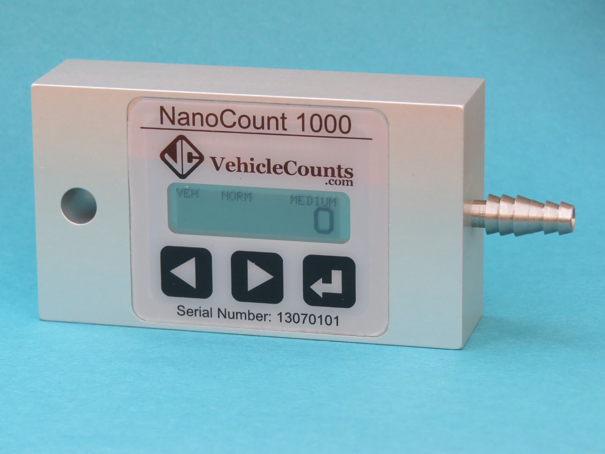
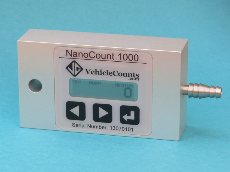
The VehicleCounts.com NanoCount 1000 vehicle counter is a single channel totalizer with a built-in LCD display. This unit is for those applications that only need total counts for a period of time. It is totally self-contained.
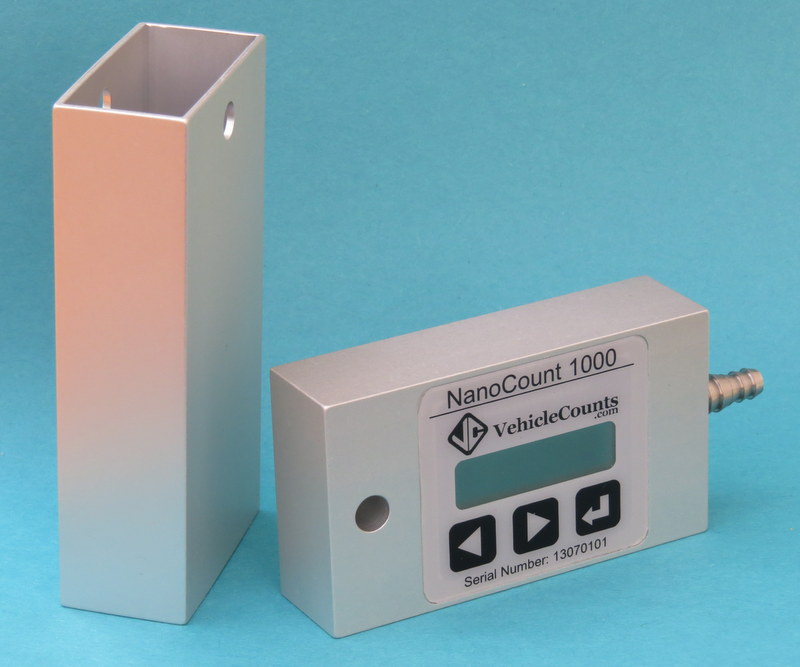
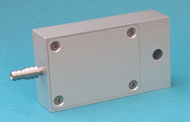
The NanoCount 1000 comes in two pieces. The main body and the protective sleeve. There is a small hole protruding through both pieces where a suitable padlock may be inserted to secure the unit and prevent the sleeve from being removed from the device. The sleeve is the first line of defense against abuse. If the sleeve becomes unusable due to damage, you may purchase spare sleeves. It is important to always have the sleeve on the unit to prevent damage to the keypad/display and to prevent unwarranted entry into the unit through the battery cover.
The unit is powered from a common CR2032 type of Lithium coin battery, available at most stores. The unit should operate at least 6 months on one battery with constant usage. There is a “CHANGE BATTERY” message that will “fllash” on the top line of the display when it is time for a new battery.
The operations section of this manual walks through all the steps of operating your NanoCount 1000 counter. Each operation is described in some detail to help you understand normal usage.
Anchor. The device used to secure the air hose to the roadway or shoulder.
Dwell. The time after a hose is “hit” before another “hit” will be recorded. Also known as deadtime, recovery time, response time, delay after hit time, etc. In the case of timestamp recording machines like the PicoCount, the dwell time can be adjusted after the data is collected to aid in cleaning up the collected data. In these machines the dwell time is automatically set to an optimal value by the choice of the type of environment you are collecting data in.
Grip. The device used to attach the air hose to the anchor device.
Hit. When a moving vehicle tire strikes a hose generating an air pulse.
Hose. Specifically, the rubber air hose (pneumatic hose) used by the NanoCount 1000 for traffic sensing.
Roadway. The active surface of the highway, road, street, or driveway that vehicles travel on.
The following trademarks are used throughout this manual:
Windows® is a registered trademark of Microsoft Corporation.
NancoCount is a trademark of R&R Technologies, Inc.
VehicleCounts.com is a trademark of R&R Technologies, Inc.
This section discusses the operation of the NanoCount 1000. It discusses how to set out the air hose and how to configure the unit for various types of counts.
The NanoCount 1000 has three different operating states:
1. Sleeping: In this state, the counter will briefly awaken each time a hose hit occurs and update the count.
2. Awake: In this state, the display will turn on, and the display will update counts when hose hits occur.
3. Menus: In this state, the display is on, and the counter does not respond to hose hits.
In addition, there is a backlight which can be useful in low light. When activated, the backlight can be turned on and off by touching the left button. Depending on the backlight duration set in the menus, the backlight can automatically turn off in 5, 10, or 20 seconds, unless you enter the Menus state while the backlight is on, in which case, the backlight stays on until the menus are exited (or timed out).
The unit will automatically enter the Sleeping state when there have been no buttons pressed for 30 seconds.
If the battery is low, the unit will “flash” the message “CHANGE BATTERY” in the Awake state. Also, when the battery is low, the backlight will not light, to preserve battery life as long as possible.
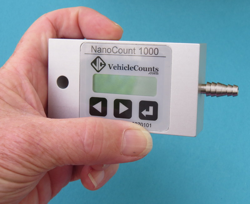
The NanoCount 1000 has three buttons directly below the display. These buttons are actually state-of-the-art electronic touch switches that sense your finger as it approaches the overlay. These switches do not need to be pushed it is sufficient to only touch the overlay where the button is indicated. If a switch does not seem to be responding simply pull your finger back and lightly re-touch the switch, applying pressure accomplishes nothing, and might degrade the instrument seals. Throughout this manual we state to “touch” the switch, rather than “press” the switch to emphasize that they only need to be lightly touched.
The one of the most important factors in getting good counts with air hose counters is in proper setting of the hoses, so that is where we start, but first a little education.
Air hose comes in a variety of sizes, shapes and materials. For traffic counting though there are only a few to consider.
Choosing a material:
All air hose used in traffic counting is made of natural rubber or a synthetic rubber referred to as EPDM.
Natural rubber is softer than EPDM rubber for a given thickness and hole size. Therefore, natural rubber is slightly easier to handle and store.
Natural rubber can be degraded by exposure to UV from sunlight, whereas EPDM has been formulated to be resistant to UV degradation.
For hot temperatures, EPDM is the preferred rubber, and for cold temperatures natural rubber is the preferred rubber. EPDM is the most popular rubber used because it performs well over a wide temperature range from hot desert conditions down to near freezing whereas natural rubber performs best from warm temperatures down to well below freezing.
For a given hose size and length, signal attenuation in natural rubber is slightly higher than EPDM, which means that EPDM is better for long hose runs.
In the USA, natural rubber is mainly considered a "winter" hose, and is mainly used in the northern latitudes.
Choosing a size and shape:
There are currenly three shapes of hose in use today; round, half-round, and dual-hose.
![]()
Round is by far the most popular and easiest to use. It is suitable for the majority of counting applications. There currently are two sizes which are most common, normal hose and mini hose.
Normal hose is about 15mm outside diameter (9/16 inch or 0.600 inch). It comes with either a 6.3mm hole (1/4 inch or 0.250 inch), or a 4.8mm hole (3/16 inch or 0.188 inch).
Mini hose is about 9.3mm outside diameter (3/8 inch or 0.365 inch). It comes with a 4.8mm hole (3/16 inch or 0.188 inch). The profiles of these three styles are summarized below:
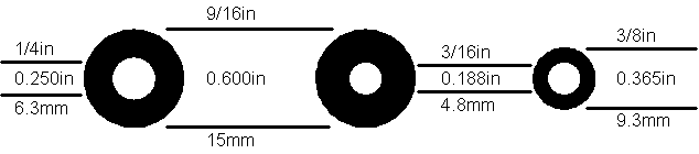
The normal hose with the 6.3mm hole has good resistance to wear and generates the strongest air pulses. It is the preferred hose in very long hose runs.
The normal hose with the 4.8mm hole is stronger, stiffer and heavier. It is intended for very heavy traffic conditions, or where there is a lot of truck traffic. It also would be the hose of choice for unimproved and gravel roads. The air pulse it generates is weaker than the hose above, so longer runs are not practical.
The mini hose is fairly recent as an air hose, but has rapidly become the hose of choice. It generates a smaller air pulse than the normal hose with the larger hole, so it is not suitable for long hose runs. It's biggest appeal is that it is quite a bit lighter and more pliable than the normal hose. If you are setting out lots of counters each day, it can save a lot of labor. The mini hose does not hold up as well to traffic wear as the normal hose.
As a rule of thumb, in a very busy count program, normal hose will usually last a full count season (in most areas a count season goes from spring through fall) before needing replacement. Mini hose on the other hand may only last half a season before needing replacement.
Half-round, because of its beefier build, finds use in very heavy traffic, where there is a lot of heavy truck traffic, or where the hoses are going to be left out for extended count times. This hose is trickier to lay down on the road, the flat side must always face the roadway, and it is pretty difficult to handle.
Dual-Hose is relatively new. It is generally constructed of two mini hoses with a webbing in between that maintains the hoses at a fixed, close, spacing. This hose must be mounted to the roadway with it's flat side against the pavement. It is more complex to attach to the roadway, and harder to handle, but is a much more reliable way to place down two hoses at one time. This hose can only be used, for speed and classifying, with the newest generation of traffic counters that have the time resolution to give satisfactory results. It is not appropriate for use with the NanoCount 1000 counter.
This section describes the various methods used to attach the hose to and near the roadway. Proper attachment of the hose is very important to getting proper counts.
Methods of Attachment:
There are a variety of methods used to attach hoses to the roadway and shoulders. We will discuss each of these methods along with their pros and cons. Attaching a hose involves two distinct operations, placing an anchor and gripping the hose.
Anchors:
An anchor is the device attached to the roadway or shoulder that the hose will be attached to.
There are several devices used for anchors. Choice of the anchor device will depend on several factors, like roadway surface material, shoulder surface material, roadway temperature, etc.
To determine the appropriate anchor device, you need to decide where the anchor points will be placed. When stringing hoses on roadways, ideally the anchoring is off the roadway surface, on the shoulders, however, this often not possible. Generally, the traffic counter unit will be mounted next to the roadway and the hoses will be strung across one, two, or more lanes of roadway. The end nearest the counter on most roadways can easily be anchored in the shoulder, except when they are cement sidewalks, or the shoulders are extremely soft, or non-existent. The far end of the hose must often be anchored in the middle of the roadway, depending on the hose configuration for the study you will be doing.
Choice of the anchoring device depends on the materials it must be mounted to. For shoulder anchoring, the materials will generally be compacted gravel and soil, or tarmac. For roadway anchoring, the materials will be tarmac or cement. Tarmac is easier to drive nails into when it is warmer whereas cement doesn't care about temperature, it is always hard.
The most common anchoring device is the nail. For tarmac roadways you would use tarmac nails, masonry nails, or PK nails. For soft shoulders you would use spikes which come in a variety of lengths from 150mm (6 inches) to 300mm (12 inches) depending on the firmness of the shoulder. You will need a pretty hefty hammer for driving in the nails or spikes. In tarmac, you can also use power nails and an anchor plate with a portable nail gun (not common, but quick).
Another form of anchoring device is the masonry screw. This would be mostly used in sites that are re-visited quite often, such as on-ramps to freeways, etc. This involves drilling a hole then hammering the screw anchor into the hole.
In tarmac in warmer climates you can directly screw into the tarmac with the proper screw and power screwdriver.
Anchoring in tarmac depends on the weather. When it is hot, the tarmac is soft and the anchoring devices must be longer to stay put. Sometimes it may be necessary to also use an anchoring plate held down by several nails. When it is cold, the tarmac can become very hard and shorter anchoring devices would be used.
Grips
A grip is the device used to attach the hose to an anchor. There are a variety of methods used for this purpose and we will discuss the pros and cons of each here. A hose has two ends, one end is terminated in the traffic counter and the other end is at the far end of the roadway or lane being measured. The grip at the roadway shoulder must attach to the hose in such a way that the hose is not pinched shut, yet it must hold the hose firmly enough that it will not slip. The grip at the far end of the hose (from the counter) simply has to hold the hose from coming loose from the anchor. We are going to discuss five different types of grips: Chinese fingers, figure-8, C-clamps, anchor-plate clamps, Nylon belt, and Nylon cord.
Chinese fingers are made from stainless steel wire formed into a patented web pattern that grips the hose in such a way that it will not pinch shut, and it will not slip. This is great for the counter end of the hose. These devices can also be very quickly attached to the hose and allow simple tension adjustment. In heavy traffic situations where you do not want to be out in the roadway any longer than possible, these devices can be a life saver. These are the highest cost grips we will discuss. In very hot climates, the rubber hose can get so soft that these types of grips can actually sever the hose since they are made from a narrow gauge stainless steel wire. You must get the correct size of grip for the hose thickness you will be anchoring. This type of grip can be attached to the anchor in two ways: You can pre-install the anchor and simply loop the anchor end of the grip over the nail-head. Once under tension, this grip will not normally pop off. The other method would be to use a large washer and drive the anchor nail through the washer and the anchor loop of the grip. This later method may be necessary in high speed traffic. However proper usage of road tape can solve the hose bouncing issue.
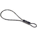
Figure-8 grips are made from a thicker gauge of stainless steel formed into a loop that is pinched near one end (looking like an unbalanced figure 8). These grips are easy to attach to the hose and adjust. They grip over a wide enough area that they normally will not pinch the hose shut. They also will hold without slipping once the hose is under tension. If the hose is bouncing a lot in traffic, slippage may occur. Appropriate application of road tape (discussed below) can prevent this. This type of grip can be attached to the anchor in two ways: You can pre-install the anchor and simply loop the anchor end of the grip over the nail-head. Once under tension, this grip will not normally pop off. The other method would be to use a large washer and drive the anchor nail through the washer and the anchor loop of the grip. This later method may be necessary in high speed traffic. For the hose end grip, you can apply some duct-tape over the grip, after it has been attached and the hose is tensioned, to prevent slippage. This type of grip is of moderate cost. This can also cut into the hose in hot temperature.
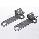
The C-clamp grip is good for the far end of the hose when it must be attached in the middle of a roadway. These grips are made of galvanized steel. This type of grip is first attached to the hose, then an anchor nail is driven through one or both of its mounting holes. You would use two holes in warmer climates when the tarmac is getting softer. This type of grip can pinch the hose shut so would not be considered for the shoulder grip. Since the anchor is installed through this grip, you must spend more time in the roadway installing it, especially if you have to drive in two anchors. This grip is of moderate cost.
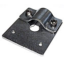
The anchor plate is used for the far end of the hose when it must be mounted in the middle of the roadway and the tarmac is very soft from hot temperatures. Anchor plates are made of a thick gauge of galvanized steel and have 4 mounting holes. You can spend considerable time in the roadway installing this type of grip, particularly if you are using all of the mounting holes. Anchor plate grips pinch the hose shut. You must specify the hose size when purchasing the anchor plate. If the anchor plate grip ever comes loose, you have a fairly good size chunk of metal loose in the roadway which could cause damage to vehicles. The anchor plate grip is moderate to high cost.
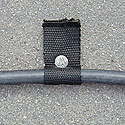
The Nylon belt grip is made by cutting off a 10 to 15 cm ( 4 to 6 inch) length of the belt, folding it around the hose and driving a nail through it into the roadway. It is only useful as a grip at the far end of the hose. It cannot prevent slippage, therefore the end of the hose has to be large enough not to slip through the grip, this is usually accomplished by tying the end of the hose into a knot (see end-plugging the hose below). This can be a low cost grip, but you have to buy a roll of the belt and cut it into grips.
Grips made of Nylon cord are very popular, namely because they are cheap. You cut off a strip of cord and literally tie the hose to the anchor. Once you get the hang of tying proper knots to prevent pinching the hose, these type of grips can be as effective as the figure-8 types of grips. This type of grip has a real advantage in very hot weather, because the Nylon is relatively soft and flattens out under tension, it will not cut into the rubber as it gets soft. This type of grip is the least expensive, but does require proper knot tying to not have problems. For the hose end grip, it is a good idea to apply some duct-tape over the knots after they have been attached and the hose is tensioned to prevent slippage.
To prevent moisture, dirt, and grit from entering the hose, the far end needs to be plugged. Moisture in the hose can block the airway, whereas dirt and grit inside the hose can cause rapid breakdown of the hose, by lacerating the inside surface when vehicles compress the hose as they are driving over it. Dirt, grit, and hose particles can eventually get vibrated all the way down to the air switches and cause the air switches to become clogged and non-functional. One exception to plugging the end of the hose is in very hot temperatures, particularly when the day to night temperature extremes are large. In this case, a very small pinhole in the end-plug is recommended to keep the air pressure inside the hose normalized. We will discuss a variety of methods to plug the end of the hose.
Tying a knot at the end of the hose. For the mini hose this is very easy to do. Depending on the stiffness of the normal hose being used, this may or may not be an option. It is a common method used. The big knot makes using C-clamps or Nylon belt grips easy, since it will not slip through them. If the hose is terminated in the middle of the roadway, the big knot might be objectionable. In very hot conditions, the knot would not accomodate a breather hole.
Hex-head bolts made of galvanized steel, stainless steel, or Nylon, which you can pick up at local hardware store, can make a good end-plug. You have to choose the proper size thread for the center hole of the hose. The hex-head makes it easy to get leverage when threading the bolt into the hose. If you are needing breather holes, this scheme will not work. These are low cost.
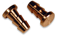
Commercial brass end-plugs. These devices are barbed and just press into the end of the hose. You have to specify what size center hole they are designed for. These can be purchased with a pin-hole for hot temperature use. These are high cost, more so when a pin-hole is needed.
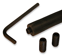
Commercial threaded end-plugs. These devices are threaded like the bolts mentioned above, but use an Allen drive to thread them in. They are made of anodized steel. They do not have the big head of the hex-head bolt, so present less of a hazard should they come loose on the roadway. You must specify what size center hole you will be plugging. These are of moderate cost.
This section will describe how to set out hose for the best results. When setting out hoses, there are a few rules of thumb to keep in mind.
After you have anchored and set down your hose, you will need to put it under tension so that it lays straight across the roadway. With normal hose, you need to pull the hose tight, then stretch it about 10% more (for a single lane, you will need to stretch it about 30cm or one foot).
If you are using mini hose, you just pull it up tight, do not attempt to stretch it.
When setting down hose, the hose is normally anchored in two spots, the far end of the hose and at the roadway shoulder on the near end. If the traffic is moving at high speeds, you may notice that your hoses are moving noticeably when vehicles travel over it. If this is the case, you will need to consider taping the hose at spots between the anchors. Mini hose tends to move easier since it is under less tension. If the wheel tracks have deep depressions, that can also make the hose move, even at moderate speeds. Note, that when taping down the hose, do not tape in the wheel tracks; avoid taping anywhere wheels would normally run over the hose.
There are two types of tape used for this purpose. Black duct-tape and Mastic tape. Both are fiberglass reinforced, both are very tough.
The Mastic tape has a very thick coating of tar and a very strong adhesive. It can be very difficult to remove at the end of a study, and leave the hose rather sticky. Being mostly tar, this tape can be left on the roadway where it will eventually merge into the roadway. This type of tape really only works well in warmer conditions where it begins merging into the tarmac. It can be applied to wet roadways that are warm, and bond well. In cold climates, it is too stiff and as a result, does not handle well, or bond well to the roadway.
Duct-tape is very thin and has a strong adhesive. This tape is easy to apply. It adheres reasonably well to clean, dry surfaces. Since it does not merge into the tarmac, it does not form nearly as strong a bond as the Mastic tape. In cold climates, it is about your only choice. It will stay down okay for a day or so, depending on traffic loads, but it is not very useful for long studies.
If you need center attachment to keep the hoses from moving and taping is not going to work, you can anchor the middle points using Nylon belt grips.
The hose can be strung across only one lane, or multiple lanes for a single count that is the sum of the traffic in all the lanes (less hose hits that are hidden by other hose hits occurring at nearly the same instant).
Single hoses stretched across multiple lanes will count quite well in low to medium traffic loads, but as the total traffic in vehicles per hour increases, the occurrences of simultaneous hits increases and as a result, the traffic volume being determined by the counter will be lower than reality. For example, at 1000 total vehicles per hour in all lanes, the total volume recorded would be about three percent low. This could actually get worse if the multi-lane counts are being done between signal lights, because the traffic would be coming in groups with the chances of simultaneous hits considerably increased.
Now that you have the hose set up on the street, you need to connect the nose to your NanoCount 1000.
First, wake up the NanoCount 1000 by touching the ↵ button on the right side below the display. The display should turn on displaying something like:
Note that the NanoCount 1000 will automatically wake up when the protective sleeve is removed. If it is left for a period of time with no activity then the display will turn off and just touching the ↵ button on the right side below the display will turn the display back on.
This is the AWAKE display. It consists of two sections, the count section which will display up to 7 digits of counts (or 9,999,999 counts), and the status section which is at the top of the display. The status line shows the type of counts being displayed, the air switch sensitivity setting, and the traffic speed setting.
In this case the count is zero, the counter is set up to count vehicles, the air switch is at normal sensitivity, and the traffic speed is set to medium (for vehicles primarily going 25 to 50 MPH (40 to 80 KPH)). The counter is now ready to begin a new count session.
If on the other hand the display shows:
The counter already has 508 counts in it. To set up for a new count you normally would want to zero the prior counts.
To zero the data count in the NanoCount 1000 use the following procedure:
1. Touch and hold the middle button below the display for 2 seconds, or until the main menu screen shows:
2. Touch the middle button (NEXT button) briefly and the following should show:
3. Touch the far right button (SELECT button) briefly and you should return to the AWAKE display with the count now zero’ed.
The NanoCount 1000 hose barb is designed to take hoses with 4.7mm to 6.3mm (3/16inch to 1/4inch) center holes. In the case of the 6.3mm (1/4inch) holes, the hose needs to be pressed all the way flush to the case to insure a good grip. For the 4.7mm (3/16inch) holes, press the hose on until it firmly resists further pressing.
Now you just need to wait for a vehicle to pass over the hose to make sure everyting is alright. If the counter registers one count per vehicle (unless the counter is set to count axles, then it should show the correct axle count), then you are good to go.
You can then just close up the counter and lock it, until you are ready to retrieve the counts.
The NanoCount 1000 has a menu system built in to allow configuring the instrument. This menu system will allow you to specify typical traffic speed, adjust sensitivity, retrieve last count, and set the counting type. The NanoCount 1000 has an LCD for displaying counts, status and menus, and 3 electronic “Touch” buttons. These touch buttons do not need to be “pressed”, there is nothing that moves; they detect your finger presence as soon as you touch the panel. These buttons will not work well if you are wearing gloves, or if the panel gets standing water on it.
Upon waking up the NanoCount 1000 by removing it from its protective sleeve, or by touching the ↵ button, you should see something like:
You then enter the Menus state by touching and holding the center button until you see the main menu screen displayed (about 2 seconds):
To navigate (move around) in the menus, the bottom line of the display shows the action of the three buttons just below. In the above screen, the left button when pressed goes to the previous menu item, the middle button goes to the next menu item and the right key selects the item.
There are currently 6 items in the main menu:
EXIT Returns to the count display screen.
CLEAR COUNT Clears the count (and stores it in Last Count if it is more than 9 counts -- see below).
TRAFFIC SPEED Allows you to set the type of environment that the counter is being used in -- see below.
COUNT TYPE Allows you to show vehicle counts or axle counts on the count display screen -- see below.
SENSITIVITY In this item you can adjust the vehicle detection sensitivity -- see below.
BACKLIGHT This item lets you specify if the backlight is to be used, and what its timeout period is -- see below.
VERSION Selecting this will show the firmware version of this unit -- see below.
LAST COUNT Allows you to see the last count recorded in the unit -- see below.
You can use the PREV or NEXT keys to scroll through the list. When the end of the list is reached, it wraps around to the first item (i.e., if you were at EXIT and pressed PREV, it would go to LAST COUNT).
Pressing SELECT here returns you to the count display screen. The main menu always begins with the EXIT selection just in case you did not really want to be in the menus.
Pressing SELECT here zeros the counter and returns you to the count display screen. If the current count was more than 9, then it will be stored in Last Count before it is zeroed -- see LAST COUNT below.
Pressing SELECT here puts you in the SPEED menu. The NanoCount 1000 can currenty be configured for 5 different traffic speed ranges:
FAST Typically for vehicles traveling greater than 50 MPH (80 KPH).
MEDIUM Typically for vehicles traveling 25 to 50 MPH (40 to 80 KPH).
SLOW Typically for vehicles traveling less than 25 MPH (40 KPH).
DRIVEWAY Typically for vehicles in driveways, entering and exiting parking lots -- 5 seconds or more between cars.
DRIVETHRU Typically for vehicles in drive-through stands -- 30 seconds or more between cars.
The choice of which traffic speed to choose will be the conditon that best describes what most vehicles are doing.
When the SPEED menu is entered, it will start with the currently active selection. You can then scroll up or down through the selections.
When you SELECT your item, it will be set as the new active selection and return you to the main menu.
Pressing SELECT here puts you in the COUNT TYPE menu. The NanoCount 1000 can display either vehicle or axle counts. Normally you would display the vehicle counts. In the NanoCount 1000 vehicle counts use suitable delays depending on the speed range specified to generate only 1 count per vehicle. The axle counts can be useful for troubleshooting (see below).
This menu only has two choices, so the NEXT button toggles between the choices. Once your choice is made with the SELECT button, you will return to the main menu.
When you SELECT your item, it will be set as the new active selection and return you to the main menu.
Pressing SELECT here puts you in the SET SENSITIVITY menu. There currently are 3 sensitivity settings for the counter:
LOW This setting would be used for very short hose runs, or if serious overcounting is occurring.
NORMAL This setting is the default and would cover most situations.
HIGH This setting would be used for long hose runs or if persistent undercounting is occurring.
This menu opens with the sensitivity setting currently specified in the counter. Upon pressing SELECT the new sensitivity will be specified for the unit and we return to the main menu.
Pressing SELECT here puts you in the SET BACKLIGHT menu. There currently are 5 timeout settings for the backlight.
If a timeout is specified, then the backlight can be turned on in the main AWAKE screen by touching the left button below the display. The backlight will then stay on for the timeout period specified, or until the unit goes to sleep because of no key activity or the sleeve is closed over the unit, whichever, occurs first. If the backlight is on, it can be turned off at any time while in the AWAKE screen by pressing the left button below the display.
NEVER Selecting this setting means the backlight will never be used.
SECONDS5 This setting will activate the backlight for 5 seconds when the the backlight button is touched.
SECONDS10 This setting will activate the backlight for 10 seconds when the the backlight button is touched.
SECONDS20 This setting will activate the backlight for 20 seconds when the the backlight button is touched.
ALWAYS This setting will turn the backlight on when the backlight button is pressed and it will stay on until it is turned off by the same button, or when the unit goes to sleep due to no keypad activity or the sleeve is slipped over the unit.
This menu opens with the backlight turned off option (NEVER) ently specified in the counter. The PREV and NEXT buttons allow you to scroll through the options. Upon pressing SELECT the new backlight timeout will be specified for the unit and we return to the main menu.
Note: If the backlight is on when entering menu mode, the backlight will stay on until you have exited the menu mode, or the unit timed out because of no keypress activity.
This menu item is selected when you would like to view the version of firmware in the unit. It is mainly here to aid in troubleshooting a problem you might be having. Firmware cannot be upgraded in the field, however, the unit can be sent in to the factory where it can be upgraded. Normally, this would not be a requirement, unless some future firmware release added a feature which you just couldn’t live without.
Choosing EXIT returns you back to the main menu.
This menu item is selected when you would like to view the last count reading. It is primarily here to help you recover the last count in the case that you inadvertently zeroed the counter before recording the last count, or if you forgot the last count.
Choosing EXIT returns you back to the main menu.
The NanoCount 1000 operates off of a single CR2032 type Lithium coin cell battery (sometimes called DL2032). This battery type is very popular and can be purchased nearly anywhere batteries are sold. These batteries are made by Energizer, Duracell, Sony, Maxell, Phillips, and Panasonic. This battery should give you at least 6 months of operation with heavy usage, and even more with light usage.
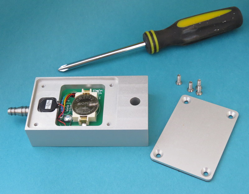
To replace the battery you will need a “Phillips” type screwdriver and a “standard” blade type screwdriver to open the battery cover. Perform this operation in a clean dry environment.
1. Remove the 4 screws on the battery cover with the Phillips screwdriver, then using the standard screwdriver, insert it into the small slot on the padlock end of the counter and pry the lid off. The gasket material we use forms a very tight fit over time, so it may take some pry pressure to get it to pop off.
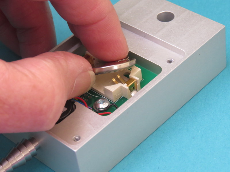
2. Notice how the battery is oriented in its holder with the “+” sign visible.
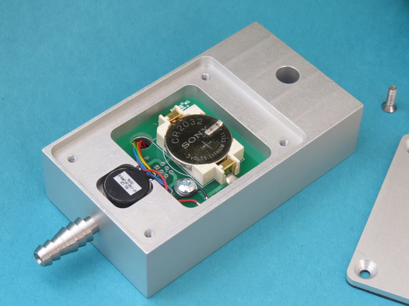
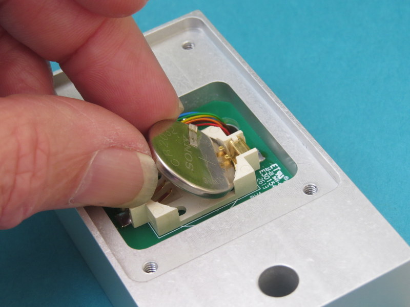
3. With your thumb, pry the battery out of the holder by lifting straight up.
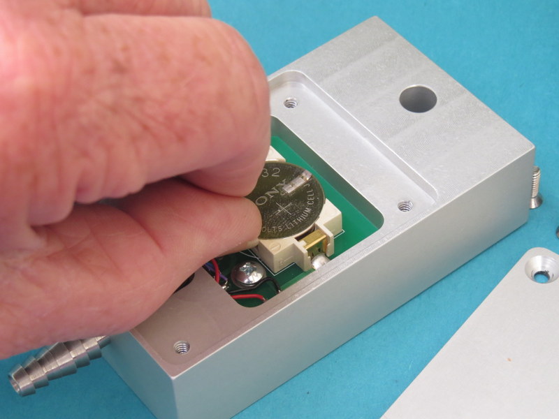
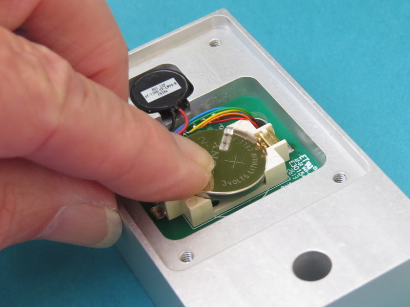
4. Slide the new battery into the holder with one side under the small metal tabs, the “+” sign on the battery should be facing up.
5. Press the battery into place. You might hear a little “click” as it seats. In any case visually check that it is properly seated (flat and just barely below the lip of the holder).
6. Flip the NanoCount 1000 over and observe that the display is showing “88888888”. This state will stay on the display for up to several minutes while it calibrates the touch switches. While it is calibrating, you can proceed to the next step.

7. If all is well, replace the battery cover and screws. Make sure that the notch on the inside of the battery cover lines up with the pry notch on the case. Also, make sure you tighten the screws sufficiently. If the covering sleeve does not slide on easily, you will have to tighten the screws more.
There are a variety of reasons that can result in count results not being what you expected. This chapter will discuss a variety of causes of unexpected results and how to remedy them.
These type of errors are mostly due to setup problems. Occasionally, even a seasoned operator can get caught by this when a normal default setting gets changed without being noticed. Generally, these errors are immediately detectable when the first vehicles drive over the hoses and the counts are off, and simply verifying that the counter speed setting is correct can fix the problem. Sometimes the errors are subtle enough that they are not detected until later when the counter is picked up.
This can be caused by a few conditions. First verify that the hose connection is nice and firm. Next check the hose for pinch points (sometimes the grip is too tight and pinches the hose shut). If all seems okay, check the hose closely for a hole, tear, or split. If all still seems okay, then try to verify that the counter is working properly, by removing the hose and gently “puffing” into the nozzle with your mouth. If the problem persists, try another counter to verify if it is the counting setup or the counter that is faulty.
This can be the result of several things.
The hose could become disconnected from the counter. Usually, the operator should note this when picking up the counter.
The hose comes loose from its anchor, and works its way to the edge of the roadway. Usually the operator should note this when picking up the counter.
The hose develops a tear or split. This would usually be on older hose. If the tear or split is small, the hose may count properly except when a vehicle tire strikes it just right, then not register counts. This may not be obvious to the operator and the bad hose may end up being used again and again before the tear becomes obvious. There is not much that can be done in this situation other than proper training so that the operators are aware that this condition can occur. The only surefire test of the hose that would detect this is a “pressure” test. For this test, you connect the hose up to a high pressure (say 40 PSI) through a gauge and a check-valve. Disconnect the pressure source and see if the hose holds the pressure.
The hose gets pinched shut. Sometimes when the operator is attaching the hose to the anchor on the counter end of the hose, the gripping device might pinch the hose shut. Maybe not right away, but with time. The symptom would be counts stopping after a period of time. This is a concern in hot weather when the hose becomes very soft. Again, operator awareness is the best remedy here.
Stringing the hose across two or more lanes. In heavy traffic, you will have increasing odds of two tires in separate lanes striking the hose at near the same time appearing to be only one hit. This will cause the totals to be less than actual. This error can become significant (more than 5%) when per lane density is 1000 vehicles per hour.
Long hose runs can cause low counts because the signal has become too weak, therefore, you may have to increase the sensitivity of the counter. This can be done via the menus (see above). However, you should first determine that the low counts are not due to one of the above situations.
This condition is the result of extra pulses on the air hoses. When a tire squeezes the hose shut, it generates a pulse of air. This air pulse travels down the hose at the speed of sound (about 1130 feet per second) until it strikes the air hose switch, which then records the hit. This air pulse after striking the air switch then reflects back towards the tire and a complex resulting air pulse can be generated depending on hose lengths. Additionally, the tire hit actually launches air pulses going both directions in the hose and when the tire leaves the hose, the air pulses going in the other direction, can now return back towards the air switch, contributing further to the air pulse complexity. Occasionally, when conditions are just right, these delayed air pulses can be strong enough to retrigger the air switch, giving double or even triple counts.
To get around this problem, most counters introduce a delay after the air switch is hit before they allow the air switch to respond to another hit. This delay is referred to as “dwell”, or “dead-time”. In the NanoCount 1000 we have a variety of counting environments you can choose from, each has its own delay time which is optimized for the counting environment selected.
Make sure you specify the correct environment for the counter. If the problem persists, select a “slower” environment to see if it improves performance. If the problem is real bad, then you may have to remove and set your hose over, possibly in a different location.
Critical counts are considered counts that are for one time events, and/or for counts at remote locations where recounting is not an option.. Any count study can go bad for any of a number of reasons as discussed above. If you are going to be doing a critical count where re-counting is not a possibility, then you should take extra precautions when running the counts. Namely redundancy, or simultaneous duplicate counts. The extra cost for running the counts is nothing compared to losing a critical count.
The first line of defense is to run at least two separate counters for each desired count. In some circumstances if lots of counters are placed out for a study, covering all the exit and entry points to an event, it may be possible to reconstruct a missing counters data, but even this can be labor intensive.
In remote locations particularly, vandalism can be an issue. Here it would pay to place the second counter nowhere near the first counter.
Power: | |
Internal Battery: | 3.0Vdc Lithium type CR2032 |
Battery Life: | 6 months typical |
Display: Type: Maximum Count: | LCD with backlight 9,999,999 |
Environmental: | |
Operating Temperature Range: | -4 F to +158 F -20 C to +70 C |
Relative Humidity: | 5 to 100% |
Water Resistance: | Yes |
Physical: | |
Dimensions: | 4.00 x 2.00 x 1.00 inches 102 x 51 x 25 mm |
Weight: | 11 oz 315 grams |
Input Air Hose: | 3/16 - 1/4 inch ID 4.75 - 6.35 mm ID |
Enclosure Materials: | Anodized Aluminum, Stainless Steel, and Lexan. |